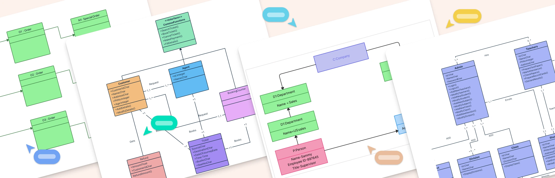
Class Diagram Definition A class diagram is a type of UML (Unified Modeling Language) diagram that visually represents the structure of a system by showing its classes, attributes, methods, and relationships. It serves as a blueprint for how different parts of an object-oriented system interact and organize data. Class diagrams are fundamental in system design because they bridge the gap between real-world concepts and code implementation. This helps developers, analysts, and stakeholders understand how the system’s components are connected and how they collaborate to perform various functions.
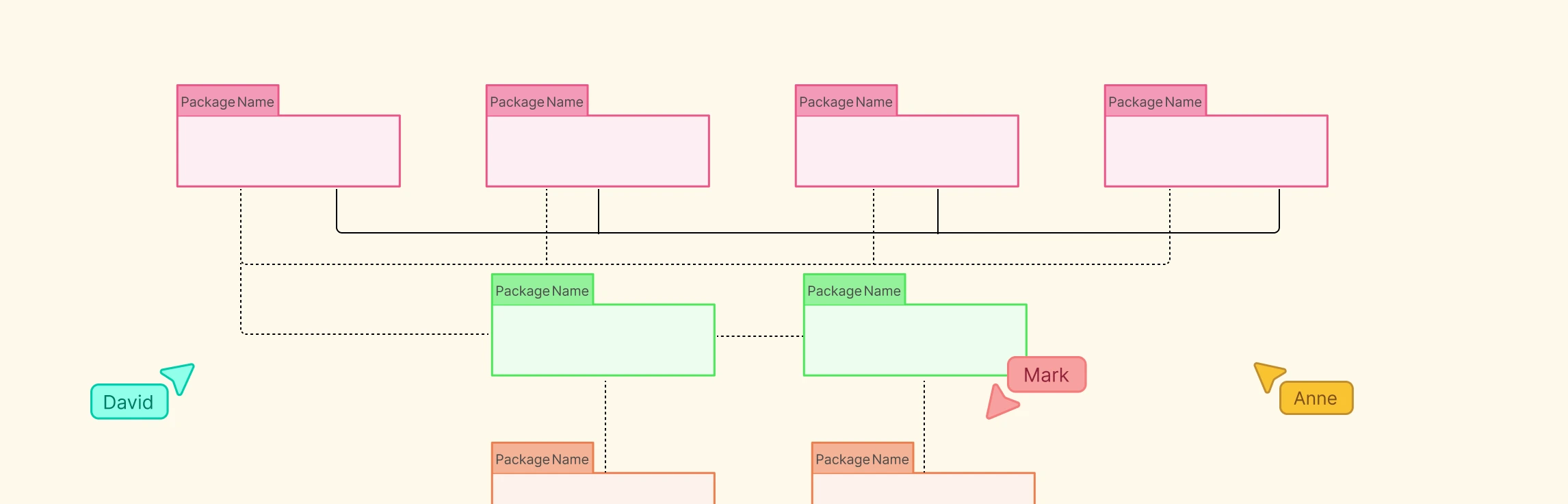
Package Diagram Definition A package diagram in UML (Unified Modeling Language) is a structural diagram that groups related elements such as classes or components into logical units called packages. It shows how these packages are organized and depend on each other, offering a clear view of a system’s structure. By grouping related parts, package diagrams simplify complex designs, promote modularity, and ensure a clean separation of responsibilities within large software systems.
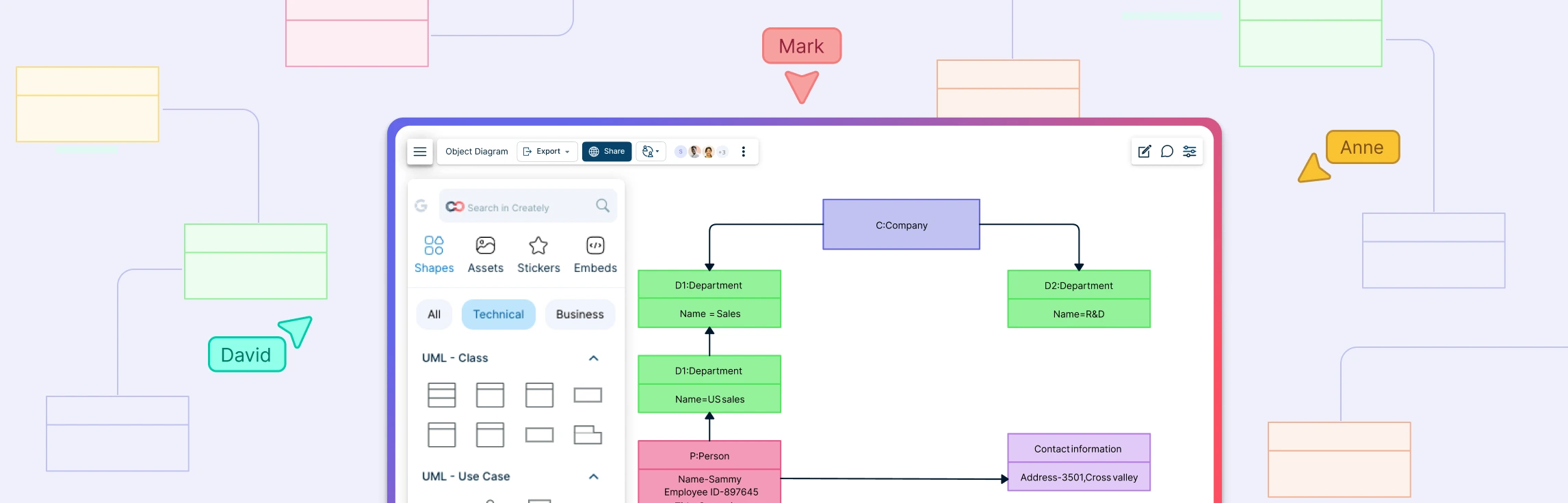
Object Diagram Definition A UML Object Diagram is a structural diagram that shows a snapshot of objects, their attributes, and relationships at a specific point in time. It represents how instances of classes interact in a real situation, reflecting the system’s state during execution. While class diagrams define the blueprint of a system, object diagrams display the actual data and connections between objects, making them useful for understanding, validating, and illustrating how a system behaves at runtime.
In the world of software design, clear visual modeling can make the difference between a well-structured system and a confusing tangle of code. Among the essential UML tools, object diagrams vs. class diagrams stand out as critical instruments for understanding both the blueprint and the real-time instances of a system. This guide will help you explore the key differences between class and object diagrams, illustrate practical examples of each, and provide ready-to-use templates so you can start modeling your software architecture with clarity and efficiency.
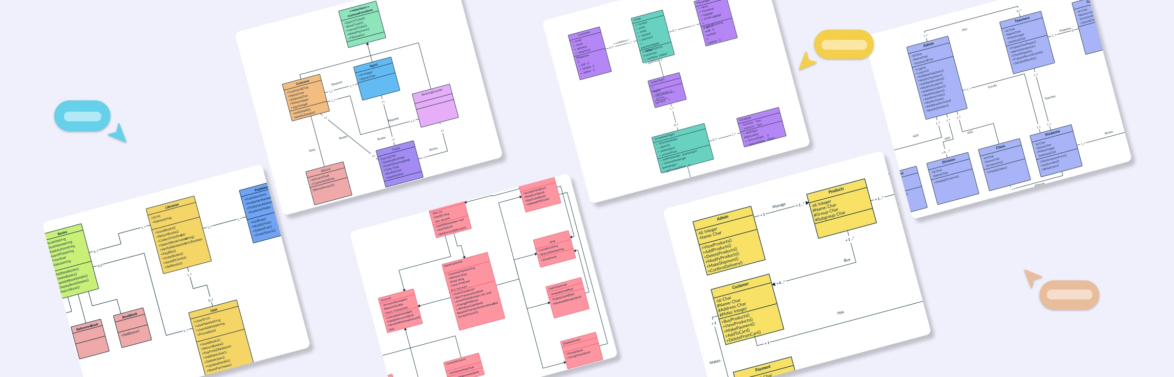
UML Class Diagrams are one of the most essential tools in software engineering, helping developers visualize the structure and relationships within object-oriented systems. They provide a clear overview of classes, attributes, methods, and how different entities interact, making them indispensable for designing, documenting, and maintaining complex applications.
UML as a subject is extremely vast, which is why this particular post is divided into two different parts. While I won’t be getting into the very basic aspects of UML diagrams today, I thought it would be pertinent to elaborate on the different types of UML diagrams and what exactly they should be used for. As most diagrammers may be aware, UML diagrams are generally divided into two main categories, i.e. Structural Diagrams and Behavioural Diagrams. While this post will concentrate on the former, expect to read all about the latter tomorrow in Part 2 of this series. So if you’re a newbie when it comes to all things UML, this really is the perfect starting point for you.
UML is a versatile visual language that is used to model a software system. The software industry has been divided in its opinion regarding the use of UML diagrams. While some see it as an integral part of software systems and development, there are a significant number of people that deem it completely unnecessary.