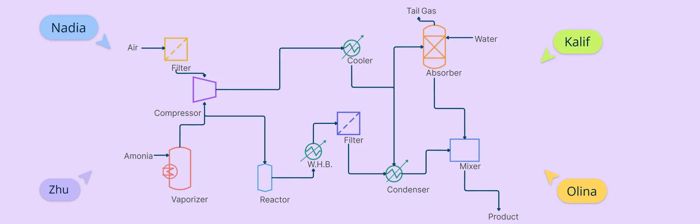
Process Flow Diagram Symbols represent the key equipment, lines, and instruments in a process, helping you visualize how materials flow through a system. Knowing these standard PFD symbols makes reading and creating PFDs easier.
PFD diagram symbols differ from P&ID symbols—PFDs show the big picture, while P&IDs include detailed piping and controls.
PFD Symbol Standards to Know
PFD symbols follow standards set by organizations like ISA (International Society of Automation) and ISO. These standards make sure everyone reads and understands the process flow diagram the same way—no matter where they’re from.
Standardization keeps diagrams clear, consistent, and easy to share.
It helps prevent mistakes when teams work on complex processes.
Some companies create custom symbol libraries but usually base them on these standards.
Categories of PFD Diagram Symbols
Creately gives you access to a full range of standard PFD symbols designed for process flow diagrams. Whether you need chemical and process engineering symbols, heating equipment, industrial machinery, or instruments, it’s all ready to use.
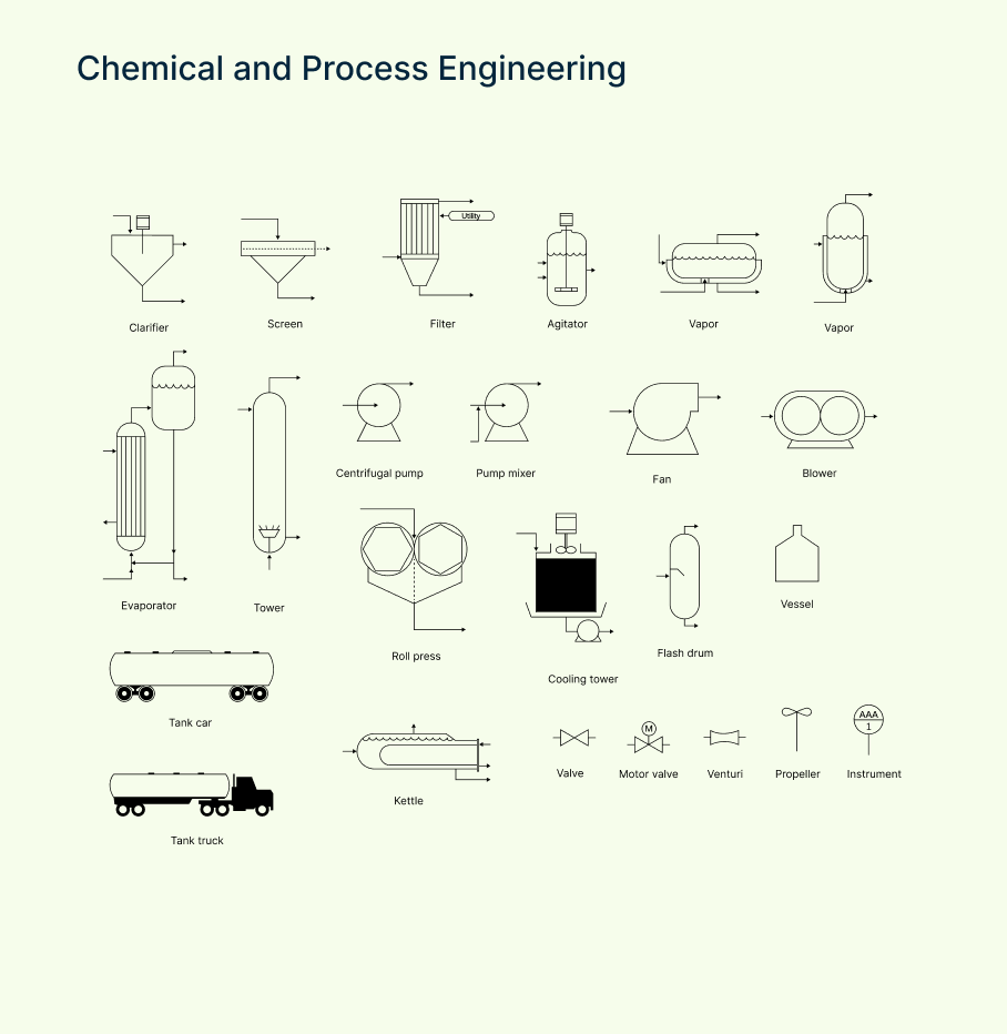
Chemical and process engineering symbols
These engineering PFD symbols represent the core equipment and components used in chemical and process industries—like reactors, separators, and distillation columns—that form the backbone of any process flow diagram.
| Symbol | Description |
| Agitator | Device used to stir or mix fluids in a tank or vessel to ensure uniformity. |
| Centrifugal pump | Pump that moves fluid by converting rotational kinetic energy into flow. |
| Clarifier | Equipment used to separate solids from liquids, often in wastewater treatment. |
| Evaporator | Unit that removes liquid by turning it into vapor, typically for concentration. |
| Filter | Device that removes solids or impurities from liquids or gases. |
| Screen | Mesh or perforated surface used to separate particles by size. |
| Tower | Tall vessel used for processes like distillation, absorption, or stripping. |
| Vapor | Symbol representing vapor or gas phase in the process flow. |
| Vapor 2 | Alternate symbol for vapor, often used to differentiate streams. |
| Blower | Mechanical device that moves air or gas at low pressure. |
| Cooling tower | Equipment that cools water by evaporative heat loss, commonly in power plants. |
| Fan | Device that moves air or gas by rotating blades, used for ventilation or cooling. |
| Flash drum | Vessel where liquid and vapor phases separate quickly due to pressure change. |
| Instrument | General symbol for measurement or control devices in the process. |
| Kettle | Vessel used for heating or boiling liquids, often with steam. |
| Motor valve | Valve operated by a motor to control fluid flow automatically. |
| Propeller | Device with rotating blades used to move or mix fluids. |
| Pump mixer | Pump combined with mixing capabilities to move and blend fluids. |
| Roll press | Equipment used to compress or flatten materials in the process. |
| Tank car | Mobile tank used for transporting liquids by rail. |
| Tank truck | Vehicle equipped with a tank for transporting liquids by road. |
| Valve | Device used to control the flow of fluids by opening, closing, or throttling. |
| Venturi | Tube with a narrowed throat that measures flow rate or creates a pressure drop. |
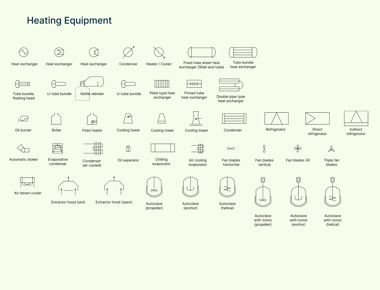
Heating equipment symbols
This set includes symbols for boilers, furnaces, heaters, and heat exchangers, showing how heat energy is added or transferred within the system.
| Symbol | Description |
| Air blown cooler | A cooling device that uses forced air to reduce fluid temperature. |
| Air cooling evaporator | Uses cool air to evaporate a liquid for heat transfer or refrigeration. |
| Autoclave anchor | Autoclave with a fixed (anchor-type) mixer for high-pressure heating. |
| Autoclave helical | Autoclave with a helical mixing element for uniform heat and pressure. |
| Autoclave propeller | Autoclave using a propeller mixer to circulate heat under pressure. |
| Autoclave with motor anchor | Motor-driven autoclave with anchor-type agitator for heating. |
| Autoclave with motor helical | Motor-driven autoclave with helical mixing for uniform processing. |
| Autoclave with motor propeller | Motorized autoclave using a propeller for mixing and heat distribution. |
| Boiler | Produces steam by heating water—used in power generation or industrial heating. |
| Condenser air cooled | Uses air to cool vapor into liquid; often seen in refrigeration systems. |
| Condenser | General symbol for converting vapor to liquid by removing heat. |
| Cooling tower | Removes heat from water by evaporation—common in industrial plants. |
| Cooling tower 2 | Alternate symbol for cooling towers, often used to show configuration variation. |
| Cooling tower 3 | Another variation of cooling tower symbol for detailed layouts. |
| Extractor hood open | An open hood that extracts heat or fumes from a process area. |
| Extractor hood slot | A slotted hood design for focused air or heat removal. |
| Fan blades horizontal | Horizontal fan blades symbol, used in heating or cooling equipment. |
| Fan blades vertical | Vertical fan blade orientation for upward/downward air movement. |
| Fan blades | Generic symbol for rotating fan components in heating/cooling systems. |
| Fired heater | Heater using direct combustion for high-temperature process heating. |
| Heat exchanger | Transfers heat between two fluids without mixing them. |
| Heat exchanger 2 | Alternate symbol for a heat exchanger, often used for clarity in complex PFDs. |
| Heat exchanger 3 | Another symbol variation for specialized heat exchanger layouts. |
| Heater | Generic symbol for equipment that raises fluid temperature. |
| Kettle reboiler | A reboiler attached to the bottom of a distillation column using steam or fluid heating. |
| Oil separator | Separates oil from water or gas using temperature and density differences. |
| Shell tube | A type of heat exchanger where one fluid flows through tubes inside a shell. |
| Triple fan blades | Symbol for equipment using three-blade fans for air movement or cooling. |
| Tube bundle floating head | Heat exchanger design allowing tube bundle removal for cleaning/maintenance. |
| Tube bundle heat exchanger | Consists of multiple tubes transferring heat between two fluid streams. |
| U-tube bundle | Heat exchanger using U-shaped tubes for compact, efficient heating. |
| Automatic stoker | Mechanism that automatically feeds fuel into a furnace or boiler. |
| Oil burner | Device that sprays and ignites oil for heating processes. |
| Plate-type heat exchanger | Uses stacked plates instead of tubes to transfer heat between fluids. |
| Chilling evaporator | Evaporates refrigerant to cool fluids—part of a refrigeration cycle. |
| Condenser (duplicate) | Same as above—removes heat to condense vapor into liquid. |
| Direct refrigerator | Cooling system where refrigerant is in direct contact with the cooling target. |
| Double pipe type heat exchanger | Two concentric pipes transfer heat between fluids flowing in opposite directions. |
| Evaporative condenser | Combines condenser and cooling tower functions for efficient heat removal. |
| Finned tube heat exchanger | Tubes with extended surfaces (fins) to improve heat transfer rate. |
| Indirect refrigerator | Uses a secondary fluid loop to transfer cooling from the refrigerant. |
| Refrigerator | General symbol for systems used to remove heat and maintain low temperatures. |
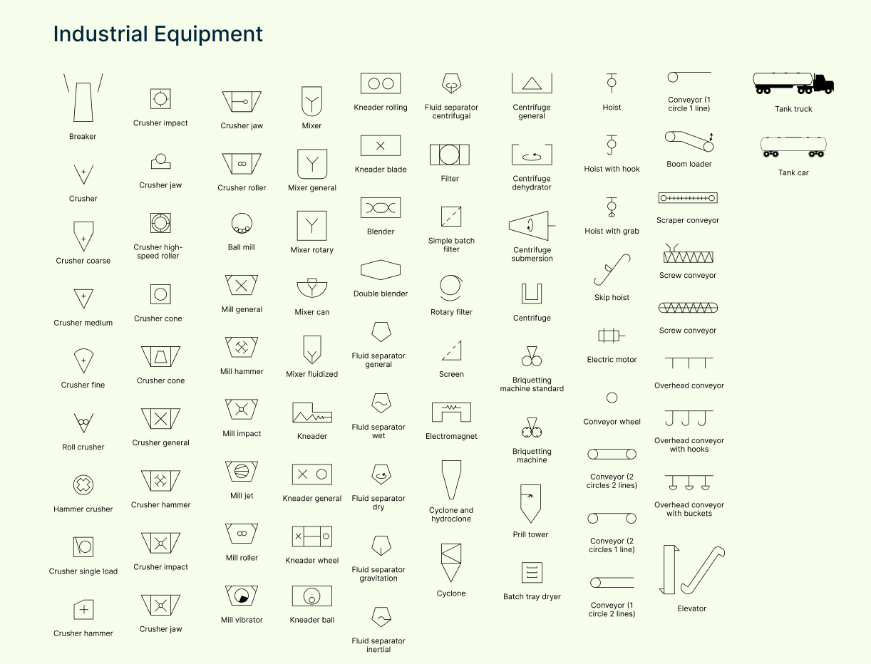
Industrial equipment symbols
These cover a wide range of machinery commonly found in industrial processes, such as compressors, mixers, crushers, and conveyors.
| Symbol | Description |
| Ball mill | A rotating cylinder used for grinding or mixing materials into fine powder. |
| Batch tray dryer | A dryer with multiple trays for drying materials in batch processes. |
| Blender | Equipment used to mix two or more materials evenly. |
| Breaker | Machine that breaks large solids into smaller chunks. |
| Briquetting machine (standard) | Compacts material into briquettes for easier handling or processing. |
| Briquetting machine | General symbol for machines that compress bulk material into uniform blocks. |
| Centrifuge (general) | Separates components based on density using high-speed rotation. |
| Centrifuge (submersion) | A centrifuge where materials are partially submerged during separation. |
| Centrifuge | Standard symbol for centrifugal separation equipment. |
| Conveyor (1 circle, 2 lines) | Symbol for a belt or roller conveyor with a single drive unit. |
| Conveyor (2 circles, 1 line) | Conveyor system with two end rollers and a single path. |
| Conveyor (2 circles, 2 lines) | Dual-path conveyor system used in complex material handling. |
| Conveyor wheel | Wheel-driven conveyor, often used for lightweight or manual transport. |
| Conveyor | General symbol for mechanical systems transporting materials. |
| Crusher (coarse) | Reduces large materials into smaller, rough fragments. |
| Crusher (cone) | Uses a cone-shaped head for secondary or tertiary crushing. |
| Crusher (fine) | Reduces material to very fine particles—used after coarse crushers. |
| Crusher (general) | Standard symbol for crushing equipment. |
| Crusher (hammer) | Uses rotating hammers to crush material—ideal for soft to medium-hard inputs. |
| Crusher (high-speed roller) | Roller-based crusher operating at high speed for fine reduction. |
| Crusher (impact) | Uses impact force to break material—common in mineral processing. |
| Crusher (jaw) | Uses two plates (one fixed, one moving) to crush materials by compression. |
| Crusher (medium) | Breaks down material to a medium size between coarse and fine stages. |
| Crusher (single load) | A batch-type crusher that handles material in one loading cycle. |
| Cyclone and hydroclone | Separates particles from fluids using rotational flow and gravity. |
| Cyclone | Device that removes particulates from gas or liquid streams by spinning flow. |
| Double blender | Dual-chamber mixer for simultaneous or staged blending. |
| Electric motor | Converts electrical energy into mechanical motion to power equipment. |
| Electromagnet | Generates a magnetic field for separation or lifting in industrial processes. |
| Fluid separator (centrifugal) | Separates fluids or particles using centrifugal force. |
| Fluid separator (dry) | Separates solids from air or gas without the use of liquids. |
| Fluid separator (general) | General symbol for devices that separate materials based on phase or density. |
| Fluid separator (gravitation) | Uses gravity to separate heavier and lighter phases. |
| Fluid separator (inertial) | Separates particles by changing flow direction rapidly to use inertia. |
| Fluid separator (wet) | Removes particulates using moisture or liquid contact. |
| Hammer crusher | Uses high-speed rotating hammers to break materials into smaller sizes. |
| Hoist with grab | Hoisting system with a grabbing mechanism for lifting bulk materials. |
| Hoist | A lifting device used to raise or lower loads vertically. |
| Boom loader | Equipment with an extendable arm for loading or moving materials. |
| Centrifuge dehydrator | Removes moisture from solids using centrifugal force. |
| Crusher jaw | Jaw-type crushing equipment for compressive breaking of materials. |
| Crusher roller | Uses rollers to crush material by compressing it between rotating cylinders. |
| Crusher | General crushing equipment for breaking down solids. |
| Filter | Removes particles from fluids using a porous medium or mesh. |
| Hoist with hook | Hoisting system using a hook for lifting and moving loads. |
| Mixer (general) | Equipment used to mix or combine materials uniformly. |
| Screen | Separates particles by size using a mesh or perforated surface. |
| Tank car | Rail-mounted tank for transporting liquids or gases. |
| Tank truck | Road vehicle with a tank body for hauling liquid cargo. |
| Kneader ball | Uses a rotating ball to knead or blend viscous materials. |
| Kneader blade | Kneading machine with rotating blades for mixing thick materials. |
| Kneader (general) | Equipment for mixing and kneading dense, heavy materials. |
| Kneader rolling | Uses a rolling action to blend materials under pressure. |
| Kneader wheel | Incorporates wheel-like elements to push and mix materials. |
| Mill (general) | Equipment for grinding or crushing materials into finer particles. |
| Mill (hammer) | Uses swinging hammers to pulverize materials. |
| Mill (impact) | Grinds materials using impact forces. |
| Mill (jet) | Uses high-velocity gas or air streams to reduce particle size. |
| Mill (roller) | Uses one or more rollers to crush or grind material. |
| Mill (vibrator) | Uses vibration to grind or separate particles. |
| Mixer can | Container-type mixer often used in batch processing. |
| Mixer fluidized | Mixes materials in a fluid-like state for uniform blending. |
| Mixer rotary | Uses rotation to blend or mix materials continuously. |
| Mixer | General symbol for a mixing unit. |
| Overhead conveyor with buckets | Suspended system with buckets for moving materials vertically/horizontally. |
| Overhead conveyor with hooks | Conveyor system using hooks for hanging or moving products. |
| Overhead conveyor | General overhead system for transporting items across a facility. |
| Prill tower | Tall structure for cooling molten material into small solid beads (prills). |
| Roll crusher | Uses compression between two rollers to reduce material size. |
| Rotary filter | Rotating drum used for continuous solid-liquid separation. |
| Scraper conveyor | Moves materials using a scraping motion along a trough. |
| Screw conveyor | Uses a rotating screw to move bulk materials horizontally or at an incline. |
| Simple batch filter | Basic filtration device used in batch processes. |
| Skip hoist | A hoisting system that lifts materials in a bucket or skip between levels. |
Instrument symbols
Instrument symbols represent sensors, gauges, and controllers that monitor and regulate temperature, pressure, flow, and other critical process variables.
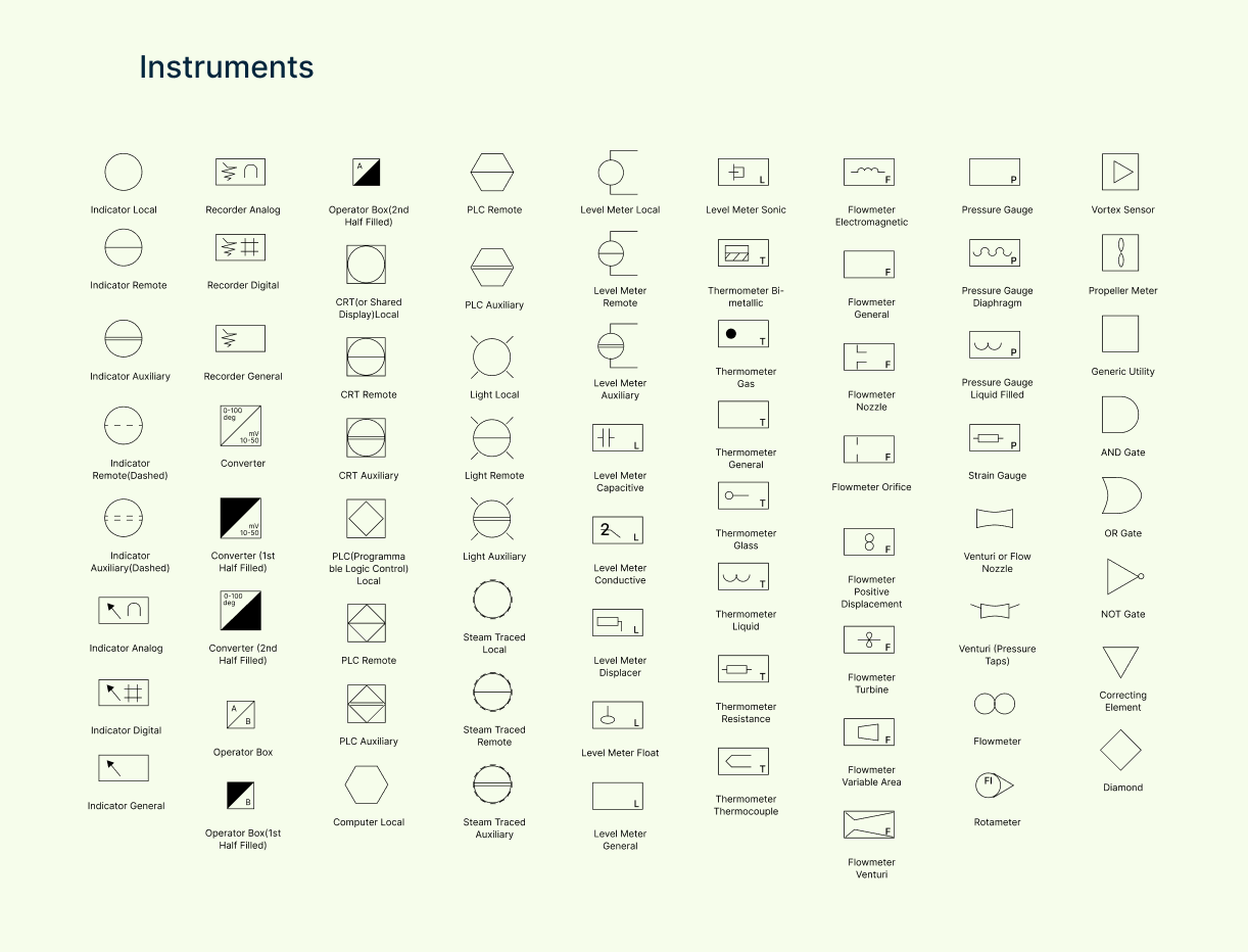
| Symbol | Description |
| Indicator local | A display located on or near the equipment to show measurements directly. |
| Indicator remote | A display located away from the equipment for remote monitoring. |
| Indicator auxiliary | A secondary indicator, often used as a backup or for less critical values. |
| Indicator remote (dashed) | Remote indicator shown as a dashed line—often optional or inactive. |
| Indicator auxiliary (dashed) | Auxiliary indicator shown in dashed style—used for reference only. |
| Indicator analog | Displays values on a scale with a needle—commonly used in mechanical gauges. |
| Indicator digital | Shows values numerically—used for digital panels or screens. |
| Indicator general | General symbol for any type of measurement display. |
| Recorder analog | Records process data on paper or analog media—like a strip chart recorder. |
| Recorder digital | Stores or displays data electronically over time—used for data logging. |
| Recorder general | Generic symbol for recording instruments. |
| Converter | Device that converts one type of signal (e.g., electrical to pneumatic). |
| Converter (1st half filled) | Shows a converter partially converting one side of the signal. |
| Converter (2nd half filled) | Alternate graphical form showing the other side of conversion. |
| Operator box | Interface for human operators to control or view processes locally. |
| Operator box (1st half filled) | Operator box showing limited control functions. |
| Operator box (2nd half filled) | Operator box with partial control or limited access interface. |
| CRT (shared display) local | Local cathode-ray display or shared interface near equipment. |
| CRT remote | Remote display terminal for process control or monitoring. |
| CRT auxiliary | Secondary remote display—often used in backup or auxiliary control rooms. |
| PLC (programmable logic control) | Local controller used for automated control of processes or machinery. |
| Computer local | A computer used on-site for monitoring or control. |
| Light local | Light indicator located at the equipment—used for status indication. |
| Light remote | Remote light indicator used to monitor system status from a distance. |
| Light auxiliary | Additional light indicator—used for alerts, warnings, or diagnostics. |
| Steam traced local | Instrument with local steam tracing to prevent freezing or maintain heat. |
| Steam traced remote | Steam-traced instrument located remotely. |
| Steam traced auxiliary | Backup or secondary steam-traced instrument. |
| Level meter local | Measures liquid level and displays it at the equipment. |
| Level meter remote | Sends level measurement to a remote display or system. |
| Level meter auxiliary | Additional level meter used as a backup or non-critical sensor. |
| Level meter capacitive | Measures level based on changes in capacitance—ideal for conductive liquids. |
| Level meter float | Uses a floating element to indicate liquid level. |
| Level meter general | Generic symbol for any type of level measuring device. |
| Level meter sonic | Measures level using sound waves—non-contact sensor type. |
| Level meter displacer | Uses a displacer element to sense level through buoyancy. |
| Level meter conductive | Detects level using electrical conductivity—used for water or liquids. |
| Thermometer bi-metallic | Measures temperature using two bonded metals that expand at different rates. |
| Thermometer gas | Uses gas expansion to indicate temperature. |
| Thermometer general | General symbol for temperature measurement instruments. |
| Thermometer glass | Traditional glass thermometer with liquid column. |
| Thermometer liquid | Measures temperature using a liquid such as mercury or alcohol. |
| Thermometer resistance | Uses changes in electrical resistance to detect temperature (RTD). |
| Thermometer thermocouple | Uses junction of two different metals to measure temperature. |
| Flowmeter electromagnetic | Uses magnetic field to measure flow of conductive fluids. |
| Flowmeter general | Generic symbol for any type of flow measuring device. |
| Flowmeter nozzle | Measures flow rate using a nozzle restriction and pressure drop. |
| Flowmeter orifice | Uses an orifice plate to measure flow by pressure differential. |
| Flowmeter positive displacement | Measures flow by trapping a fixed amount of fluid and counting cycles. |
| Flowmeter turbine | Measures flow using a spinning turbine inside the pipe. |
| Flowmeter variable area | Measures flow based on the height of a float in a tapered tube. |
| Flowmeter venturi | Uses a venturi tube to create pressure difference and measure flow. |
| Flowmeter | Generic label for flow measurement devices. |
| Rotameter | Type of variable area flowmeter with a float inside a vertical tube. |
| Vortex sensor | Detects vortices shed by flow around a bluff body to measure flow rate. |
| Propeller meter | Measures flow using a small propeller or paddle wheel. |
| Pressure gauge | Measures pressure in a system and displays it, often in psi or bar. |
| Pressure gauge diaphragm | Uses a flexible diaphragm to sense and indicate pressure. |
| Pressure gauge liquid filled | Pressure gauge filled with liquid to dampen vibrations and improve accuracy. |
| Strain gauge | Measures mechanical strain by change in electrical resistance. |
| Venturi or flow nozzle | Measures flow by constricting pipe diameter and measuring pressure change. |
| Venturi (pressure taps) | Includes pressure tap points for measuring pressure drop across a venturi. |
| Generic utility | Represents a general utility (e.g., air, water, steam). |
| AND gate | Logic gate that outputs only if all inputs are true. |
| OR gate | Logic gate that outputs if at least one input is true. |
| NOT gate | Logic gate that outputs the opposite of the input signal. |
| Correcting element | Represents an adjustment mechanism that changes process output. |
| Diamond | Typically used to show decision points in logic or control. |
| Auxiliary | Indicates secondary or backup instrumentation. |
| Remote | Shows a device located away from the main equipment. |
Pump symbols
These symbols denote different types of pumps that move fluids through the system, including centrifugal pumps, positive displacement pumps, and more.
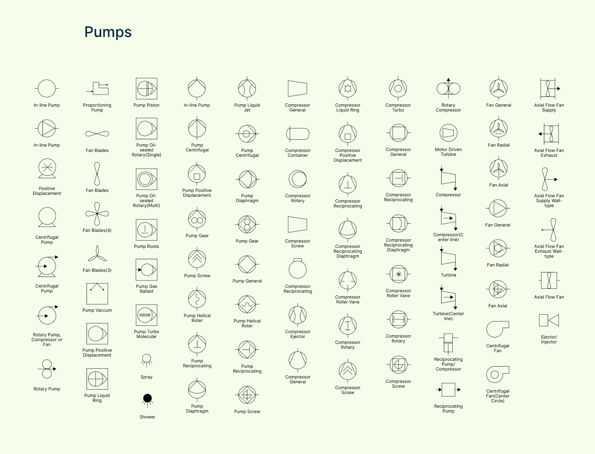
| Symbol | Description |
| In-line pump | A pump installed directly in the pipeline—compact and space-saving. |
| Positive displacement pump | Moves a fixed volume of fluid per cycle—ideal for high-pressure systems. |
| Centrifugal pump | Common pump that uses centrifugal force to move liquids efficiently. |
| Rotary pump, compressor, or fan | General symbol for rotating machines used to move fluids or gases. |
| Rotary pump | Uses rotating parts to displace fluid—good for steady, low-pulse flow. |
| Proportioning pump | Precisely adds or mixes fluids in controlled ratios. |
| Fan blades | Represents rotating fan blades—used for ventilation or forced airflow. |
| Pump vacuum | Used to draw a vacuum or reduce pressure in a system. |
| Pump liquid ring | A rotary pump with a liquid ring seal—used in vacuum applications. |
| Pump piston | Reciprocating pump using a piston to displace fluid. |
| Pump oil-sealed rotary (single/multi) | Oil-lubricated rotary vacuum pumps—used for clean vacuum generation. |
| Pump Roots | Type of positive displacement pump using meshing lobes—often for air/gas. |
| Pump gas ballast | Vacuum pump with gas ballast to handle condensable vapors. |
| Pump turbo molecular | High-vacuum pump used in precision processes (e.g., semiconductor). |
| Spray / Shower | Dispenses fluid as a spray or shower—used for cleaning or cooling. |
| Pump gear | Uses rotating gears to move fluid—commonly in hydraulic systems. |
| Pump screw | Screw-shaped rotor displaces liquid—good for viscous fluids. |
| Pump helical rotor | Uses helical rotors for continuous, smooth flow—good for food, chemicals. |
| Pump reciprocating | Moves fluid with a back-and-forth motion—high pressure, low flow. |
| Pump diaphragm | Uses a flexible diaphragm—good for corrosive or shear-sensitive fluids. |
| Pump general | General symbol for any unspecified pump. |
| Pump liquid jet | Uses a jet of liquid to move another fluid—common in vacuum systems. |
| Compressor general | General symbol for compressing gases. |
| Compressor container | Compressor housed in a container—used in modular or mobile setups. |
| Compressor rotary | Uses rotating motion to compress gases—efficient and quiet. |
| Compressor screw | Uses two rotating screws to compress air or gas—ideal for continuous flow. |
| Compressor reciprocating | Piston-driven compressor—used for high pressure applications. |
| Compressor ejector | Jet-based compressor that uses motive fluid to compress another. |
| Compressor liquid ring | Sealed with a rotating liquid ring—ideal for vapor-heavy or contaminated air. |
| Compressor positive displacement | Moves a fixed volume of gas—includes piston and screw types. |
| Compressor diaphragm | Compresses gas using a flexible diaphragm—ideal for clean gas streams. |
| Compressor roller vane | Uses vanes in a rotating drum—smooth and quiet operation. |
| Compressor turbo | High-speed compressor that uses dynamic action—used in process gas services. |
| Rotary compressor | Rotating unit used in smaller-scale or refrigeration systems. |
| Compressor (center line) | Same as above, drawn with a center reference line—common in schematics. |
| Turbine | Converts fluid or steam energy into mechanical work—drives pumps/compressors. |
| Turbine (center line) | Same as above with centerline indicator—for clarity in complex diagrams. |
| Motor-driven turbine | Turbine driven by an external motor, often for hybrid systems. |
| Reciprocating pump/compressor | Combined symbol—device can act as pump or compressor based on application. |
| Fan general | General fan symbol used for ventilation or forced air movement. |
| Fan radial | Fan with blades that push air outward from the center—used in HVAC. |
| Fan axial | Fan that moves air along the axis—common in ducts or exhausts. |
| Centrifugal fan | Fan that moves air using centrifugal force—ideal for high flow, low pressure. |
| Centrifugal fan (center circle) | Same as above with stylized drawing for center detail. |
| Axial flow fan (supply) | Blows air into a system—used in intake or fresh air systems. |
| Axial flow fan (exhaust) | Draws air out of a system—used in ventilation and exhaust systems. |
| Axial flow fan (supply wall-type) | Wall-mounted fan supplying air into a space. |
| Axial flow fan (exhaust wall-type) | Wall-mounted exhaust fan—common in enclosed or confined spaces. |
| Ejector / Injector | Jet-based device that moves fluid using another high-speed fluid stream. |
Valve and fitting symbols
Valves control flow within the process, and this category includes various valve types like gate, globe, check valves, plus fittings and connectors essential for directing flow paths.
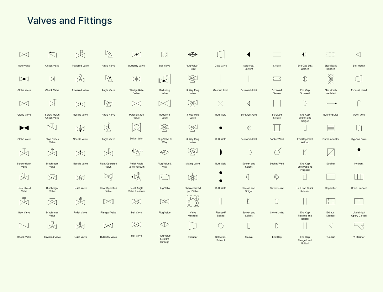
| Symbol | Description |
| Gate Valve | A valve that opens/closes by lifting a gate—used for on/off flow control. |
| Screw-down Valve | Valve closed by turning a screw—precise shutoff and throttling. |
| Lock-shield Valve | Tamper-resistant valve, often used for fixed settings in heating systems. |
| Reel Valve | Specialized valve used to control hose or reel-based systems. |
| Check Valve | Allows fluid to flow in one direction only—prevents backflow. |
| Screw-down Check Valve | A check valve with added screw mechanism for manual control. |
| Stop Check Valve | Combines features of stop and check valves—can shut off and prevent backflow. |
| Diaphragm Valve | Uses a flexible diaphragm to control flow—ideal for corrosive fluids. |
| Powered Valve | Valve operated using electric, pneumatic, or hydraulic actuators. |
| Needle Valve | Offers precise flow control through a narrow opening. |
| Relief Valve | Automatically releases pressure to prevent equipment damage. |
| Angle Valve | Redirects flow at a 90-degree angle—used where space is limited. |
| Float Operated Valve | Opens/closes based on liquid level using a float—common in tanks. |
| Flanged Valve | Valve with flanged ends for bolted connections—easy to remove or replace. |
| Butterfly Valve | Quick shutoff valve using a rotating disc—used in large pipes. |
| Wedge Gate Valve | A gate valve with a wedge-shaped gate for better sealing. |
| Parallel Slide Valve | Gate valve with two sliding gates for smooth operation and reduced wear. |
| Swivel Joint | A joint that allows rotation to prevent stress on connected pipes. |
| Relief Angle Valve (Vacuum) | Releases vacuum pressure safely to avoid collapse or damage. |
| Relief Angle Valve (Pressure) | Releases excess pressure at a right angle—space-saving design. |
| Ball Valve | Uses a rotating ball to open/close flow—quick, reliable shutoff. |
| Reducing Valve | Automatically reduces pressure to a set level downstream. |
| Plug Valve 3 Way | Three-way plug valve that directs flow to multiple ports. |
| Plug Valve L Way | Plug valve shaped like an “L” for directing flow between two paths. |
| Plug Valve | Simple on/off valve using a cylindrical plug. |
| Plug Valve Straight Through | Flow moves straight through with no directional change. |
| Plug Valve T Point | Plug valve with T-shaped paths for diverting or mixing flow. |
| 3 Way Plug Valve | Three-port plug valve for mixing or diverting flow. |
| Mixing Valve | Combines two streams into one—used to control temperature or composition. |
| Characterized Port Valve | Specially shaped valve port for accurate control at low flow rates. |
| Valve Manifold | A group of valves in one block for centralized control. |
| Reducer | Connects two different pipe sizes—reduces flow diameter. |
| General Joint | Generic connection between two pipes or fittings. |
| Butt Weld | Welded joint where two pipe ends are joined directly. |
| Flanged/Bolted | Pipe joint using flanges and bolts—easy to disassemble. |
| Soldered/Solvent | Joint made with soldering (metal) or solvent welding (plastic). |
| Screwed Joint | Threaded connection—quick to assemble or remove. |
| Socket and Spigot | One pipe end fits into another—commonly used in drainage. |
| Sleeve | Short pipe section for joining two ends together. |
| Screwed Sleeve | Sleeve with internal threads for connecting pipes. |
| Socket Weld | Pipe fits into a socket and is welded—provides a strong, leak-proof joint. |
| End Cap | Closes the end of a pipe—basic sealing element. |
| End Cap Butt Welded | Welded cap that permanently closes off a pipe end. |
| End Cap Screwed | Threaded end cap that can be removed easily. |
| End Cap Socket and Spigot | Cap that fits onto a spigot end—common in plastic piping. |
| End Cap Fillet Welded | Cap welded with a fillet seam—strong and often permanent. |
| End Cap Screwed and Plugged | End cap with a removable plug for draining or inspection. |
| End Cap Quick Release | Easily removable cap for fast access to pipe ends. |
| End Cap Flanged and Bolted | Cap attached with flange and bolts—secure but removable. |
| Electrically Bonded | Ensures electrical continuity across joints—used for safety. |
| Electrically Insulated | Breaks electrical path to prevent grounding or corrosion. |
| Bursting Disc | Safety device that ruptures under pressure to release excess force. |
| Flame Arrester | Prevents flames from traveling backward through piping—used in flammable systems. |
| Strainer | Filters debris or solids from the flow—protects downstream equipment. |
| Separator | Removes phases (liquid/gas or solid/liquid) from the process stream. |
| Exhaust Silencer | Reduces noise in exhaust lines—common in compressed air or steam systems. |
| Tundish | A small funnel used to control liquid flow—often used in casting or drainage. |
| Bell Mouth | Flaring pipe opening that reduces resistance at entry or exit. |
| Exhaust Head | Directs exhaust gases safely and prevents rain entry—used on vertical outlets. |
| Open Vent | An open connection to atmosphere—used to relieve pressure or allow air entry. |
| Syphon Drain | Uses siphon action to remove fluid from tanks or systems. |
| Hydrant | Connection point for water access—used in safety and utility systems. |
| Drain Silencer | Reduces noise when draining high-pressure liquids or steam. |
| Liquid Seal Open/Closed | Maintains a seal using liquid—prevents gas or vapor from escaping. |
| Y Strainer | Angled strainer that traps debris in a mesh basket—easy to clean. |
Vessel symbols
Vessel symbols show tanks, drums, reactors, and other containers that hold or process fluids and gases within the system.
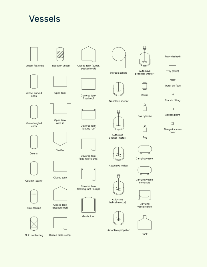
| Symbol | Description |
| Vessel (flat ends) | General vessel with flat ends—used for basic storage or mixing. |
| Vessel (curved ends) | Vessel with rounded ends—helps handle pressure and improve flow. |
| Vessel (angled ends) | Ends are angled to allow better drainage or flow direction. |
| Column | Tall vertical vessel used for separation processes like distillation. |
| Column (seam) | Column with seam line—indicates construction detail or tray alignment. |
| Tray column | Column containing trays to separate phases—common in distillation. |
| Fluid contacting | Vessel where two phases (e.g., liquid-gas) come into contact to interact. |
| Reaction vessel | Container where chemical reactions occur—can be heated, pressurized, or stirred. |
| Open tank | Basic tank exposed to atmosphere—used for storage or mixing. |
| Open tank with lip | Open tank with extended edge or overflow lip. |
| Clarifier | Tank designed to settle and separate solids from liquids (sedimentation). |
| Closed tank | Sealed tank used for storing or processing under controlled conditions. |
| Closed tank (peaked roof) | Tank with a pointed roof—helps with runoff or gas accumulation. |
| Closed tank (sump) | Closed tank with a bottom section to collect settled material. |
| Closed tank (sump, peaked roof) | Tank with both a peaked roof and sump for full drainage and separation. |
| Covered tank (fixed roof) | Enclosed tank with a non-moving roof—used for liquids and low-pressure gas. |
| Covered tank (floating roof) | Tank with a roof that floats on the liquid surface to reduce vapor loss. |
| Covered tank (fixed roof, sump) | Sealed tank with a sump and fixed roof. |
| Covered tank (floating roof, sump) | Floating roof tank with a sump—handles volatile liquids and sediment. |
| Gas holder | Large tank used to store gases under variable pressure. |
| Storage sphere | Spherical vessel for storing pressurized gas or volatile liquids. |
| Autoclave anchor | Reactor with fixed anchor agitator—used for pressure/temperature processes. |
| Autoclave anchor (motor) | Anchor-type autoclave with a motorized agitator. |
| Autoclave helical | Autoclave with a helical agitator for mixing thick fluids. |
| Autoclave helical (motor) | Helical autoclave powered by a motor. |
| Autoclave propeller | Reactor vessel with a propeller agitator—for fast or turbulent mixing. |
| Autoclave propeller (motor) | Motor-powered propeller-type autoclave. |
| Barrel | Cylindrical container—often used for liquids or bulk storage. |
| Gas cylinder | High-pressure container for storing compressed gases. |
| Carrying vessel | Transportable vessel used for moving fluids within a plant. |
| Carrying vessel (moveable) | Mobile vessel with wheels or handles—used for internal transport. |
| Carrying vessel (cargo) | Vessel designed for shipping or bulk transport. |
| Tank | Generic symbol for a fluid-holding container. |
| Tray (dashed) | Represents a tray inside a column—dashed for optional or variable use. |
| Tray (solid) | Solid tray layer inside a column—used for separation and phase contact. |
| Water surface | Symbol showing the level of liquid—used for level indication. |
| Branch fitting | Connection point where pipes or vessels branch out. |
| Access point | Location where maintenance or inspection access is available. |
| Flanged access point | Access port with a flanged connection for secure opening/closing. |
Process annotation symbols
These symbols help add important notes, labels, stream numbers, and data boxes, providing clarity and additional information to the PFD.
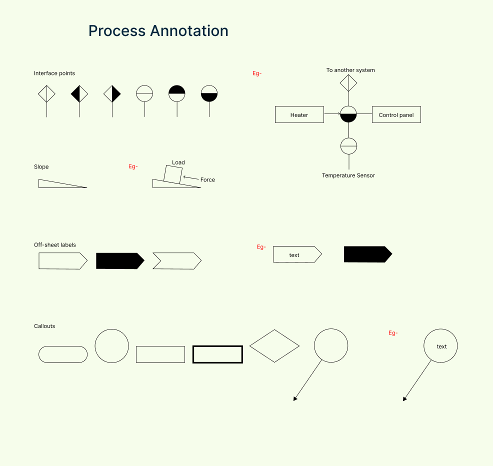
| Symbol | Description |
| Interface points | Shows where the process connects with another system, unit, or diagram. |
| Slope | Indicates a sloped line or pipe to show gravity flow or elevation change. |
| Off-sheet labels | Marks where the process continues on another page or sheet—helps track flow. |
| Callouts | Used to add explanations, stream numbers, operating data, or notes to elements. |
Free Ready-to-Use Process Flow Diagram Templates
Water Treatment Process Flow Diagram


Process Flow Diagram Engineering

Sewage Treatment Process Flow Diagram

Cement Production Process Flow Diagram

Process Flow Diagram Chemical Engineering

References
www.sciencedirect.com. (n.d.). Process Flow Diagram - an overview | ScienceDirect Topics. [online] Available at: https://www.sciencedirect.com/topics/engineering/process-flow-diagram.
Nikos Filipu (2019). The Process Flow Diagram as an Aid in Academic Writing. International Conference celebrating the 65th birthday of Professor Todor Shopov entitled ‘The Pedagogy of Good Opportunities for Education for all’ held on 22 November 2017. [online] Available at: https://www.researchgate.net/publication/333339834.
FAQs About Process Flow Diagram Symbols
What is a process flow diagram (PFD)?
How are PFD symbols different from P&ID symbols?
How do I use PFD symbols correctly?
Where can I find standard PFD symbol libraries?
How do I use PFD symbols in Creately?
Can I customize or import my own symbols in Creately?
How do I keep my PFD readable when using many symbols?