In industries like chemical, mechanical, and process engineering, diagrams help teams plan, design, and run complex systems. Two key diagrams are the process flow diagram and the piping and instrumentation diagram ( PFD and P&ID).
A PFD shows the big picture—major equipment and how materials flow through the process. A P&ID dives into the details—piping, valves, instruments, and control systems. Knowing the difference helps engineers and operators work safely, design efficiently, and keep processes running smoothly.
What Is a Process Flow Diagram (PFD)?
A process flow diagram (PFD) is a visual representation of a plant’s main processes. It shows the major equipment and how materials and energy move through the system, but it doesn’t include minor piping or detailed controls. PFDs help engineers understand the overall process and plan designs efficiently.


Who uses PFDs?
PFDs are mainly used by process engineers, project managers, and designers to get a clear picture of the workflow, identify bottlenecks, and coordinate planning.
Common elements in a PFD
Some of the key PFD symbols include,
Major equipment symbols (reactors, pumps, heat exchangers)
Flow arrows showing material movement
Major control loops at a high level
Flow rates or block flows (optional, depending on the detail needed)
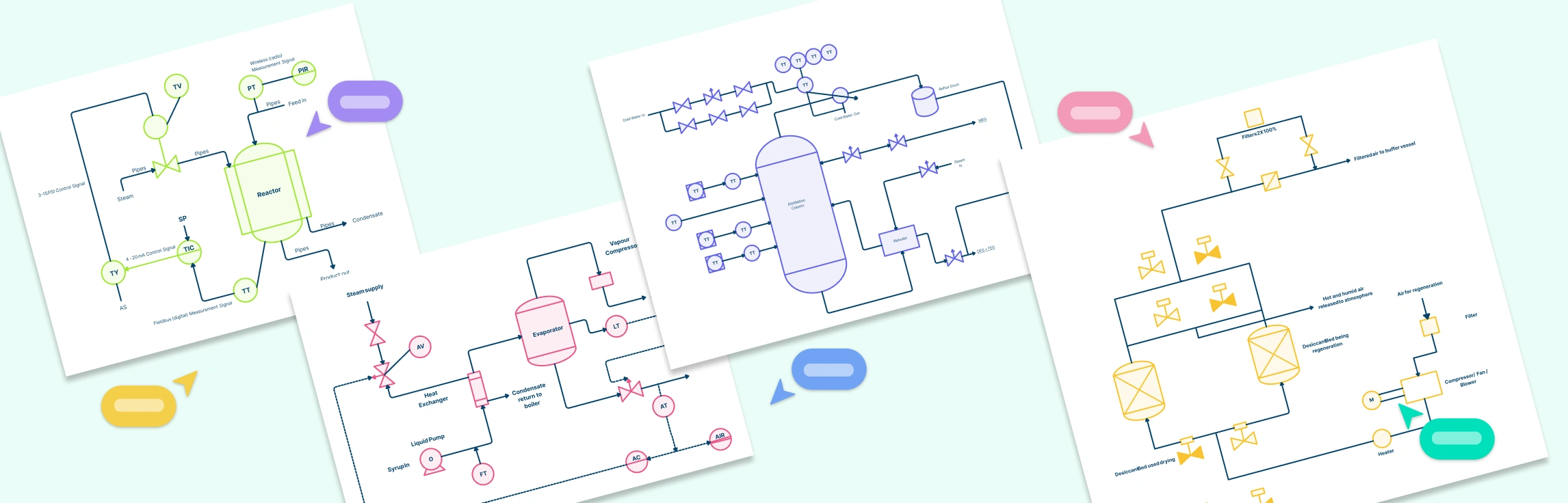
What Is a Piping & Instrumentation Diagram (P&ID)?
A piping and instrumentation diagram (P&ID) is a detailed schematic that shows how all the piping, valves, instruments, and control systems connect in a plant. It includes line numbers, materials, and equipment IDs, making it a key reference for designing, building, and maintaining processes.
Who uses P&IDs?
P&IDs are mainly used by mechanical engineers, instrument and control specialists, construction teams, and maintenance staff. They rely on P&ID examples to install equipment correctly, troubleshoot issues, and ensure safe operations.

Common elements in a P&ID
Piping specifications (material, size, line numbers)
Valve types and tags
Instrument tags and loop IDs
Fittings, relief valves, and other safety devices
Equipment IDs (pumps, tanks, reactors, etc.)
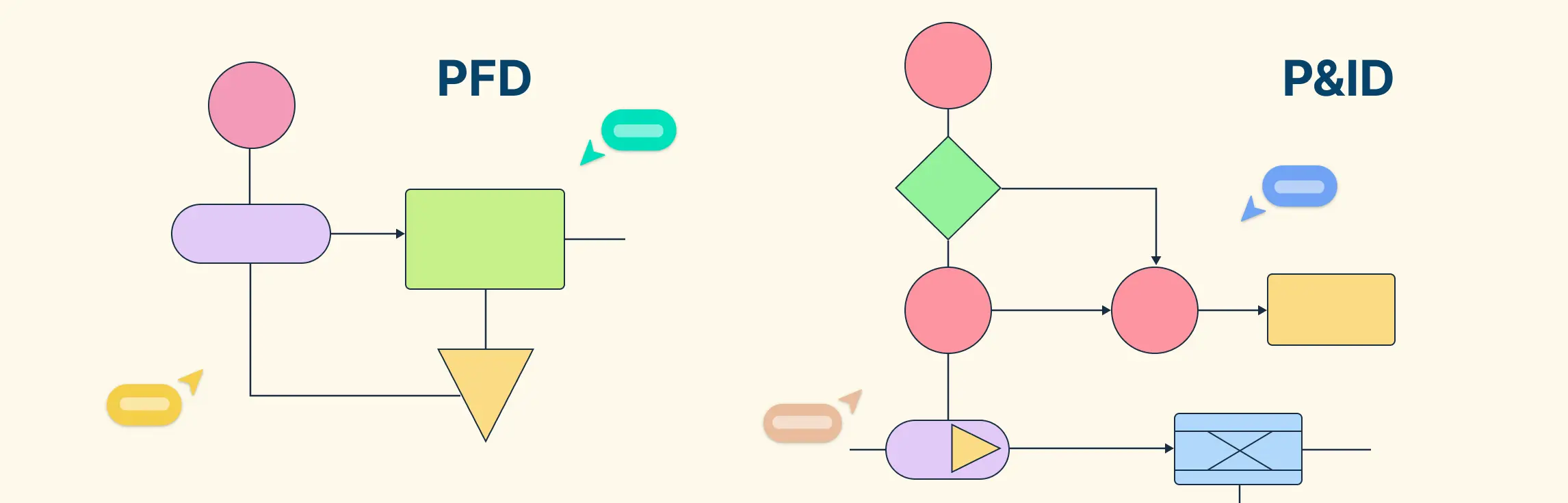
Difference Between a P&ID and a PFD
While both PFDs and P&IDs are used in process and chemical engineering to represent plant systems, they serve very different purposes.
- PFDs focus on the big picture: showing major equipment and how materials or energy move through the process. They are simpler, easier to read, and help engineers plan and understand overall workflows.

- P&IDs focus on the details: every pipe, valve, instrument, and control loop is shown. They are essential for construction, operation, and maintenance, providing precise instructions for building and controlling the system.

The difference exists because each diagram supports a different stage of the engineering lifecycle. PFDs guide design and process understanding, while P&IDs ensure safe, accurate implementation and operation.
| Attribute | Process Flow Diagram (PFD) | Piping & Instrumentation Diagram (P&ID) |
| Purpose | Shows overall process flow and major equipment | Shows detailed piping, instruments, valves, and control loops |
| Detail level | High-level overview | Very detailed |
| Audience | Process engineers, project managers, designers | Mechanical engineers, instrument & control engineers, construction & maintenance teams |
| Equipment shown | Major units (reactors, pumps, heat exchangers) | All equipment, including minor devices, instruments, and safety devices |
| Piping | Only major connections | All pipes with specifications, line numbers, and materials |
| Valves & instruments | Generally not shown | All valves, control devices, and instrument tags |
| Control loops | High-level overview only | Detailed loop diagrams with tags and control logic |
| Flow rates & energy data | Often included | Typically included if needed for control or safety |
| Lifecycle stage | Design planning, process overview, simulations | Detailed engineering, construction, operations, maintenance |
| Standards | General industry symbols, simple flow arrows | ISA, ANSI/ISO standards for instrumentation and piping |
| Update frequency | Rarely updated once finalized | Frequently updated during construction, commissioning, and operation |
| Use in decision-making | Helps understand and optimize process | Guides installation, control, troubleshooting, and safety compliance |
| Created by | Process engineers, usually during the conceptual and design stages | Created by a team including process, mechanical, and instrument engineers; reviewed for accuracy and safety compliance |
How PFDs and P&IDs Fit into the Engineering Design Flow
1. Start with a Block Flow Diagram (BFD)
Think of the block flow diagram as a rough sketch of the process.
Only shows major process units (like reactors, tanks, or pumps) and how materials move between them.
Used in the concept stage to plan the process and communicate ideas.
2. Create a Process Flow Diagram (PFD)
Creating a PFD adds more detail to the BFD and helps visualize the process clearly.

Shows major equipment, main process flows, and energy or material balances.
Helps process engineers and project managers understand how the system works overall.
PFDs are still high-level, so minor pipes and valves are not shown.
3. Develop the Piping & Instrumentation Diagram (P&ID)
The P&ID is built from the PFD template.
Shows everything in detail: all pipes, valves, fittings, instruments, and control loops.
Used by mechanical engineers, instrument/control teams, and construction/maintenance crews.
Ensures that the system can be built, operated, and maintained safely.

4. Understand the flow from concept to implementation
BFD → PFD → P&ID represents moving from general idea → overview → detailed instructions.
Each step adds more detail and serves a different audience: BFD for planners, PFD for designers, P&ID for builders and operators.
FAQs About P&ID and PFDs
Which diagram should I use first?
Can a PFD replace a P&ID?
Why are PFDs important in engineering?
Why are P&IDs important in engineering?
Are PFD and P&ID used in all industries?