Understanding the internal workings of a system is crucial for software designers, architects, and developers. A UML composite structure diagram offers a detailed view of how components, parts, ports, and roles interact within a system, making it easier to design modular, maintainable, and scalable solutions. Whether you’re modeling software architecture, system workflows, or component-based designs, these diagrams help bridge the gap between static class definitions and dynamic interactions, providing clarity and improving collaboration across teams.
Definition of Composite Structure in UML
A composite structure in UML shows the internal organization of a system or class and how its parts interact. It is a key tool in composite structure design and modeling a composite structural system.
Unlike other structure diagrams, which focus on static relationships, a composite structure diagram highlights parts, ports, roles, and connectors inside a system, giving a clear view of component interactions. This makes it ideal for designing complex, modular systems efficiently.
When and Why to Use Composite Structure Diagrams
UML composite structure diagrams are essential for modeling systems where understanding internal collaborations and runtime interactions is critical. They help bridge the gap between static type definitions and dynamic behaviors, making them invaluable for composite structure design and visualizing a composite structural system.
Complex Internal Collaborations
Composite structure diagrams are ideal for systems where multiple components interact in intricate ways. Examples include workflow engines, communication protocols, and distributed systems. These diagrams reveal coupling patterns, inter-component dependencies, and interaction flows, helping designers identify potential bottlenecks, redundant connections, or integration issues before implementation.
Detailed Design Phases
During detailed system design, these diagrams provide clarity on how components or objects will integrate at runtime. They show which parts communicate directly, which roles they fulfill, and how data or control flows between them. This reduces ambiguity, ensures consistency with system requirements, and improves the efficiency of composite structure design, saving time and effort during coding.
Pattern Documentation and Reuse
Composite structure diagrams are highly effective for documenting structural patterns like delegation, proxies, and composite objects. By visualizing how responsibilities and behaviors are distributed across parts, these diagrams facilitate knowledge sharing, design reuse, and adherence to best practices in software architecture. They also help teams maintain consistency in composite structural systems across multiple projects.
Stakeholder Communication and Collaboration
These diagrams provide a clear, visual representation of internal system behavior for both technical and non-technical audiences. Architects can illustrate system design to developers, while managers or business stakeholders can understand the modular structure and interactions without delving into code. This fosters better alignment, informed decision-making, and smoother collaboration across teams.
Testing and Validation Support
Composite structure diagrams are also valuable for identifying test cases and validation paths. By mapping interactions, ports, and roles, QA teams can design tests that ensure all components communicate correctly, enhancing system reliability and reducing runtime errors in a composite structural system.
Purpose of Composite Structure Diagram
The primary purpose of a UML composite structure diagram is to let designers and developers “peek inside” a system or object to understand its internal makeup. It reveals how a class or component is structured internally by showing its parts, ports, and the relationships between nested elements.
Through this level of detail, a composite structure diagram in UML helps illustrate that objects are often compositions of other classified objects, each contributing specific functions or behaviors. It goes beyond external interactions to model how components collaborate internally, making it a vital tool for composite structure design and building a clear composite structural system.
By visualizing these internal connections, teams gain a deeper understanding of system behavior, dependencies, and communication paths—essential for designing efficient, modular, and maintainable architectures.
Key Components of a UML Composite Structure Diagram
A composite diagram in UML provides a detailed view of a system’s internal structure, showing how parts work together within a structural diagram. Understanding its key components is essential for effective composite structure design and building a robust composite structural system.
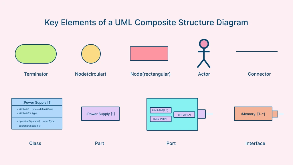
Parts/Components
Parts, also called components, represent the individual classes or objects that make up the system. Each part encapsulates specific functionality or data, acting as a building block of the overall composite structure design. Identifying and defining these components clearly is crucial for modularity and maintainability.
Connectors
Connectors define the relationships and communication pathways between components. They indicate how parts interact, exchange data, or send signals, ensuring that the composite structural system functions cohesively. Connectors can be uni-directional or bi-directional, depending on the system’s requirements.
Ports
Ports are interaction points on a component, specifying how it communicates with other parts of the system. They allow for modular connections, making it easier to update or replace parts without affecting the entire structure. Ports are especially useful in complex systems where components interact dynamically.
Terminator
The terminator symbol represents the start and end points within a UML composite structure diagram. It marks where a process or interaction begins and concludes, helping define the boundaries of system behavior and improving clarity when modeling composite structural systems.
Node
A node represents an event, milestone, or control point within a composite structure. Each node is often labeled or numbered to indicate sequence or state transitions, allowing designers to trace the flow of interactions between internal components and external systems.
Actor
An actor represents any external entity, such as a person, device, or system, that interacts with the composite structure from outside its boundary. In a composite structure diagram in UML, actors define how external elements communicate with internal components through specific ports and interfaces, ensuring clear interaction mapping.
Class
A class groups together objects with shared properties, behaviors, and relationships. Within a UML composite structure diagram, classes provide the foundation for modeling internal parts and roles, supporting a structured approach to composite structure design. They define how similar objects behave and interact within the system.
Interface
An interface specifies a contract or set of behaviors that a component, class, or system agrees to implement. In a composite structure diagram, interfaces ensure standardized communication between connected elements. They help define interaction protocols within a composite structural system, enabling modularity and easier system integration.
By combining these elements, a UML composite structure diagram provides a comprehensive view of the system’s internal architecture, helping developers, architects, and system designers create well-organized, scalable, and maintainable software systems. This level of detail makes composite structural diagrams invaluable for modeling complex applications, component-based designs, and enterprise-level systems.
UML Composite Structure Diagram Examples
To better understand UML composite structure diagrams and their practical applications, it’s helpful to look at examples and templates that illustrate real-world systems. These diagrams provide a clear view of internal parts, ports, roles, and connectors, making complex composite structural systems easier to design and maintain.
1. UML Composite Structure Diagram Template
This template provides a ready-to-use framework for creating composite structure diagrams. It includes placeholders for parts, ports, connectors, and roles, helping designers and developers quickly model composite structure design for any system. Templates are especially useful for teams that need consistency across multiple projects.


2. Bank ATM UML Composite Structure Diagram Example
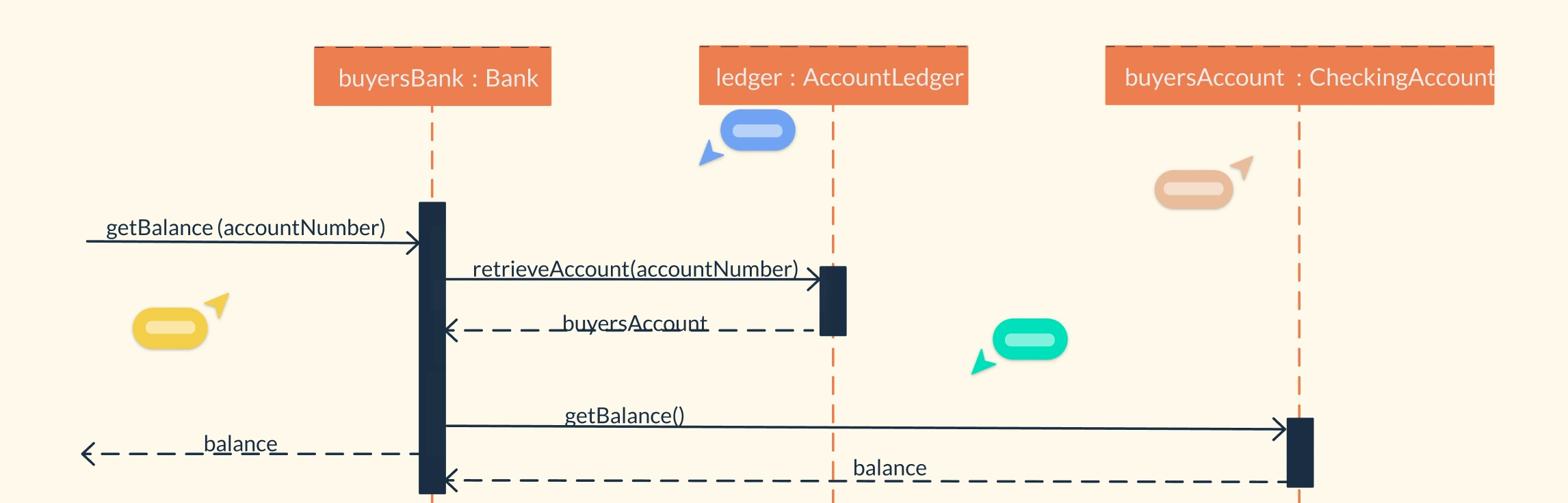
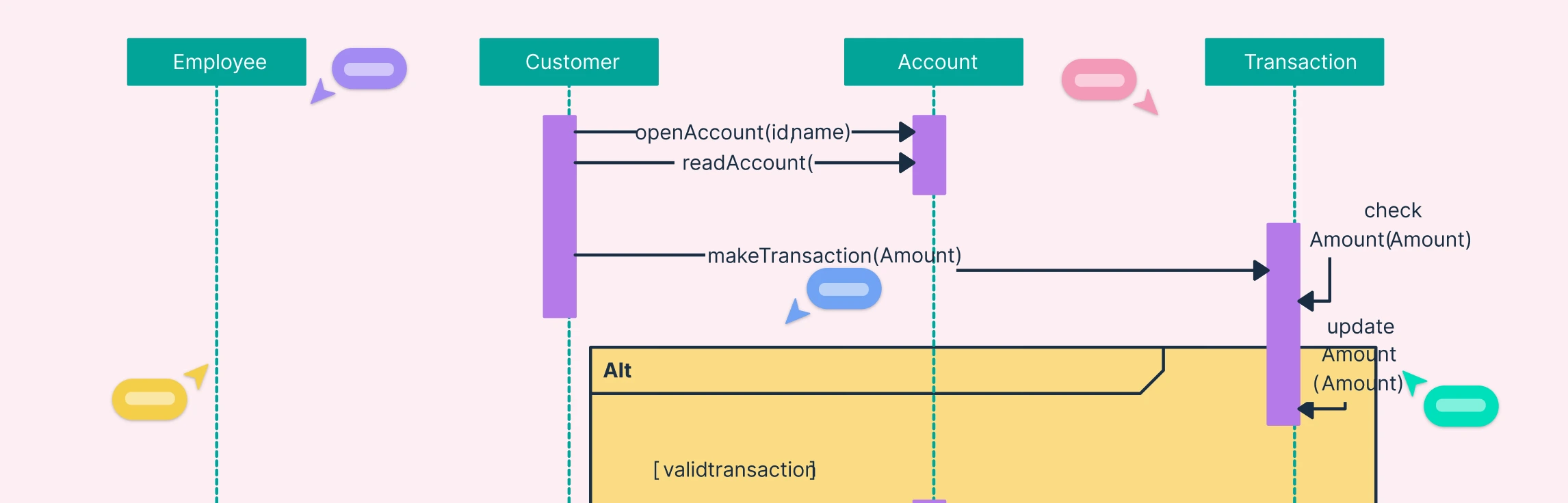
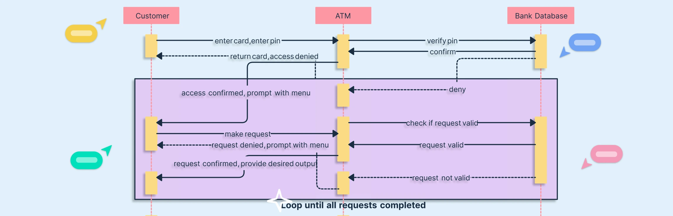
This example demonstrates a composite structure diagram in UML for a banking ATM system. It shows components such as the card reader, cash dispenser, transaction processor, and user interface, along with their connectors and roles. Such a diagram highlights how the ATM’s internal components collaborate to process transactions securely and efficiently.

3. Apache Tomcat 7 Server UML Composite Structure Diagram Example
A composite structure diagram example for the Apache Tomcat 7 server illustrates how server components—like the connector, engine, host, and servlet container—interact. This example helps system architects visualize internal structures and relationships within composite structural systems, making deployment and maintenance more manageable.

4. Computer System Composite Structure Diagram Example
This diagram provides a realistic example of a computer system’s internal architecture. It includes components such as the CPU, memory, I/O devices, and buses, showing how they communicate through defined ports and connectors. Such examples are perfect for understanding composite structure design in hardware-software integrated systems.

Composite Structure Diagram vs. Class Diagram
While both composite structure diagrams and class diagrams are structural diagrams in UML, they serve different purposes. A class diagram provides a high-level view of the system’s static structure, showing classes and their relationships. In contrast, a composite structure diagram dives deeper, revealing the internal composition and interactions within a class or component at runtime.
Aspect | Composite Structure Diagram | Class Diagram |
| Purpose | Shows the internal structure of a class or component and how its parts collaborate at runtime. | Represents the static structure of a system, including classes, attributes, methods, and relationships. |
| Focus | Focuses on internal composition and runtime interactions between parts of a class. | Focuses on the overall organization and hierarchy of the system’s classes. |
| Level of Detail | More specific and detailed — captures the inner workings and object interactions. | More general and abstract — provides an overview of the system structure. |
| Use Case | Ideal for modeling detailed behaviors, internal connections, and collaborations within a system. | Best for defining system architecture and class relationships at a high level. |
| Representation | Includes parts, ports, connectors, roles, and interfaces. | Includes classes, associations, attributes, and operations. |
| When to Use | When you need to illustrate how objects within a class work together to perform a function. | When you want to outline what classes exist and how they are related structurally. |
Mastering UML composite structure diagrams can transform how you design and communicate complex systems. By visualizing the internal organization of components and their interactions, you can improve system clarity, streamline collaboration, and create robust composite structural systems. Ready to start designing your own UML composite structure diagrams? Try Creately’s UML Diagram Software today and explore customizable templates to simplify your workflow.