When working on complex systems, sequence diagrams can quickly turn into a tangled web of interactions, especially when multiple components or subsystems need to communicate. If you’ve ever found yourself squinting at overlapping message lines or losing track of how data moves between diagrams, you’re not alone. That’s where sequence diagram gates come in. These clever UML elements simplify message passing between diagrams, helping you keep your models clean, modular, and easy to understand. In this guide, we’ll break down what sequence diagram gates are, how they work, and how you can use them to create clearer, more efficient UML diagrams.
What Is a Gate in a Sequence Diagram?
A sequence diagram gate in UML is a connection point that allows messages to enter or leave a sequence diagram frame. Think of it as a simple mechanism that enables communication between two sequence diagrams without overcrowding one with too many message links.


Each gate acts as a “portal” for message exchange; one diagram sends information through an entry gate, and another receives it through an exit gate. This approach keeps your diagrams clean while maintaining logical connections between different system parts. Using a dedicated Sequence Diagram Tool makes it easy to add gates, lifelines, and messages, keeping your diagrams clean and organized.
💡 In short, a sequence diagram gate simplifies the flow of messages between diagrams and their broader context.
Types of Gates in Sequence Diagrams
There are two main types of gates used in UML sequence diagrams: entry gates and exit gates.
1. Entry Gate
An entry gate in a sequence diagram is where messages from outside the frame enter into the diagram. For example: entry gate: getBalance(accountNumber)
Here, the message getBalance is an entry gate that receives the parameter accountNumber.
There are two types of Entry Gates:
1.1 Actual Gate
The actual gate connects one sequence diagram to another. It sits on the outer edge of the interaction and allows messages to pass in or out of the diagram to the one it references.
Essentially, it’s the “real-world” connector between two diagrams.
Example: When one sequence diagram calls another (e.g., Check Balance → Process Transaction), the message passes through an actual gate.
1.2 Outer CombinedFragment Gate
The outer combined fragment gate sits on the outside edge of a combined fragment and connects to its inner gate. It represents the external side of message flow, the part that interfaces with the rest of the sequence diagram.
Example: An outer gate might capture how a system outside a par fragment triggers one of its parallel flows.
2. Exit Gate
An exit gate in a sequence diagram allows messages to leave the frame, returning data or signaling an outcome.
Example: exit gate: return balance
This exit gate sends the balance variable back to the calling diagram.
There are two types of Exit Gates:
2.1 Formal Gate
The formal gate acts as the counterpart to the actual gate, located inside the referenced diagram. It receives incoming messages from the calling interaction (via the actual gate) and processes them within its own context.
Example: In the Process Transaction diagram, a formal gate would receive the message getBalance(accountNumber) from the calling diagram.
2.2 Inner CombinedFragment Gate
This gate appears inside a combined fragment (like alt, loop, or par). It connects messages within the fragment to message ends that lie outside of it. Essentially, it handles the “internal” side of message flow in conditional or parallel sequences.
Example: An inner gate might represent how a message from within a loop interacts with lifelines outside that loop.
🧩 Entry and exit gates work together to ensure smooth data flow between multiple UML sequence diagrams, improving clarity and reusability.
How to Use a Gate in a Sequence Diagram
Follow these steps to model a sequence diagram gate in your UML design:
Step 1. Identify the Interaction Boundary
Determine where your sequence diagram needs to send or receive messages from external diagrams or systems. Understanding these boundaries ensures your gates connect the right points and maintain logical flow.
Step 2. Place the Gate
Add a small circle or labeled connector on the frame’s edge to represent an entry or exit gate. This visually indicates where messages enter or leave the sequence diagram.
Step 3.Connect the Message
Link the gate to the appropriate lifeline inside the diagram. This ensures that messages flow correctly from the gate to the interacting element within the sequence diagram.
Step 4. Label Clearly
Use meaningful and descriptive names for your gates and messages, such as getBalance, updateRecord, or returnStatus. Clear labels make diagrams easier to understand and maintain.
Step 5. Verify the Message Flow
Check that all incoming and outgoing gates correspond correctly between diagrams. Proper verification ensures that messages are routed accurately and interactions between diagrams remain consistent.
🧠 Pro Tip: Use gates when you want to show modular communication between systems or subsystems instead of showing all interactions in one large diagram.
Sequence Diagram Gate Example
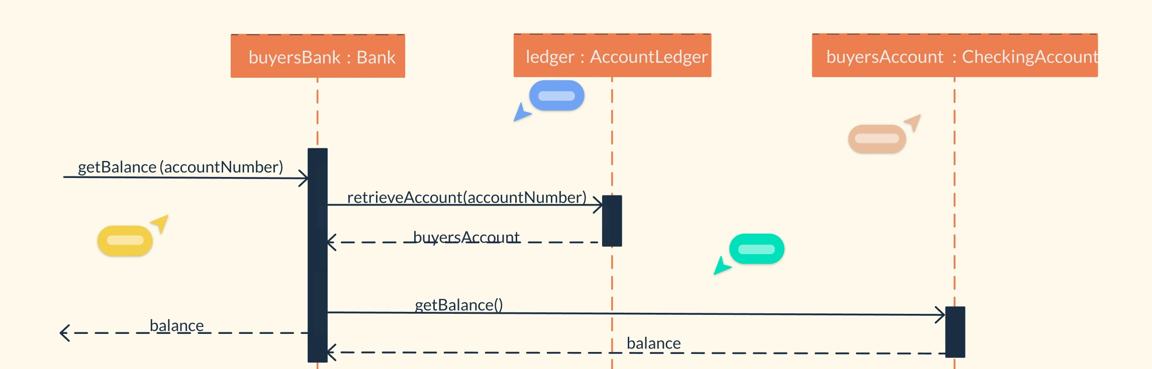
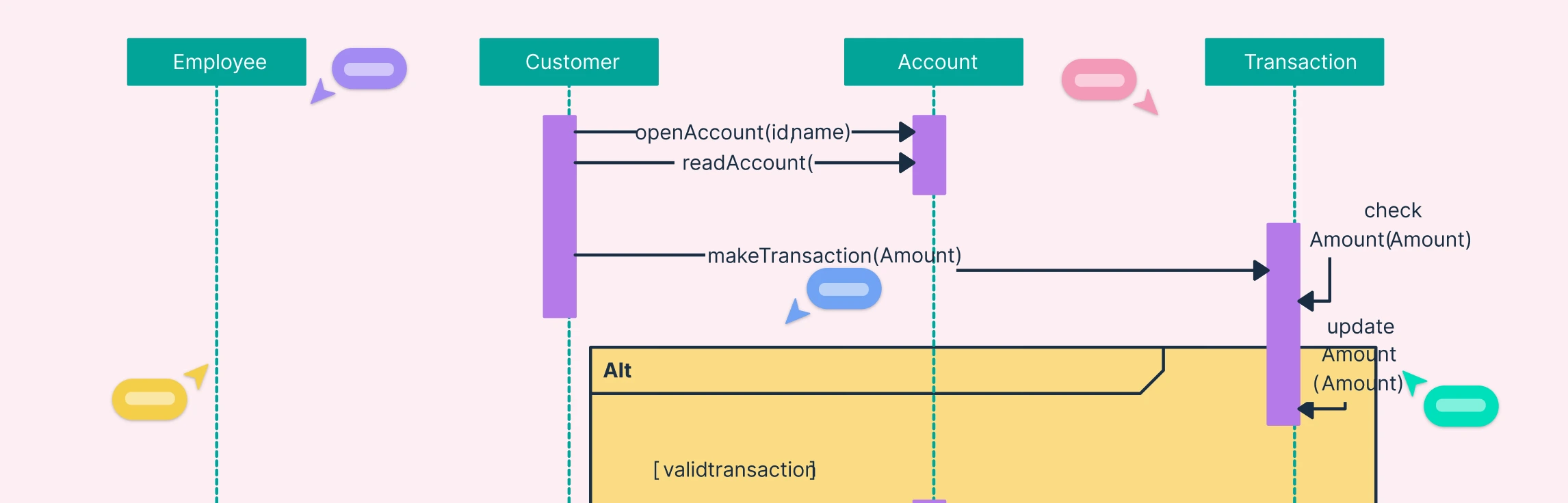
Let’s take an example from a banking system.
Imagine we have a getBalance message sent from one sequence diagram to another.
In this case:
- The entry gate is
getBalance(accountNumber)- a message entering the diagram. - The exit gate is
balance- a message leaving the diagram, returning the result.
This setup demonstrates how one diagram can request data from another while keeping each diagram logically independent and easy to maintain.

Why Use Gates in Sequence Diagrams?
Using gates in sequence diagrams offers several practical advantages:
- Simplifies complex systems: Reduces clutter when multiple diagrams interact.
- Enhances modularity: Makes each diagram reusable and easier to understand.
- Improves clarity: Clearly shows system boundaries and external interactions.
- Supports collaboration: Developers can work on separate diagrams without confusion.
When modeling large systems, gates are invaluable for connecting diagrams efficiently and maintaining visual consistency.
Create Sequence Diagrams with Gates Using Creately
You don’t have to start from scratch. Creately makes it easy to model UML sequence diagram gates with intuitive drag-and-drop tools.
- Use pre-made sequence diagram templates
- Add entry and exit gates with labeled connectors
- Collaborate with your team in real-time
- Export or embed your diagram anywhere
Try it yourself. Build your Sequence Diagram with Gates in Creately and visualize system interactions like a pro. Mastering the use of sequence diagram gates helps you create cleaner, modular, and more understandable UML diagrams. Whether you’re designing a single system or mapping interactions across multiple subsystems, gates make the process smoother and more scalable.