Modeling complex systems or software is easier when you use the right language, which is why UML and SysML are so useful. This guide looks at why each is used—UML for software design, SysML for systems engineering—and compares their diagram types, use cases, and real-world applications to help you choose the best approach for your project.
Understanding the Key Differences Between UML and SysML
| Feature | UML (Unified Modeling Language) | SysML (Systems Modeling Language) | Key Differences |
| Definition | UML is a standardized modeling language used to visualize, design, and document software systems through diagrams that capture both structure and behavior. | SysML is an extension of UML tailored for systems engineering, used to model software, hardware, data, and processes in complex systems. | UML focuses on software system representation, while SysML expands UML concepts to cover multidisciplinary system modeling. |
| Purpose / Focus | Primarily software-centric; focuses on object-oriented design and system behavior. | Broader systems engineering focus; covers software, hardware, processes, and multidisciplinary systems. | UML is best for software design; SysML is designed for complex systems involving multiple domains. |
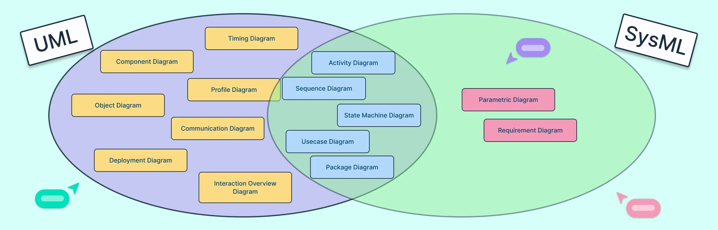
| Diagram Types | 14 diagrams: class, sequence, activity, use case, state machine, component, deployment, object, communication, package, interaction overview, timing, profile, composite structure. | 9 diagrams: block definition, internal block, requirement, parametric, use case, activity, sequence, state machine, package. | Shared diagrams: activity, sequence, use case, state machine, package. Unique to UML: class, component, deployment, object, communication, interaction overview, timing, profile, composite structure. Unique to SysML: block definition, internal block, requirement, parametric. |
| Modeling Approach | Focuses on software components, classes, and interactions. | Focuses on complete system modeling, including hardware, software, processes, and requirements. | UML is software-oriented; SysML integrates multiple engineering domains. |
| Requirements Modeling | Limited; typically handled via notes or external documents. | Built-in requirement diagram; links requirements directly to system elements. | SysML provides formal requirement modeling; UML does not. |
| Performance & Analysis | Limited support; primarily structural and behavioral modeling. | Supports parametric diagrams for constraint modeling and performance analysis. | SysML allows performance and constraint modeling; UML focuses on structure and behavior. |
| Complexity & Learning Curve | More diagrams and detailed notation; can be complex for large systems. | Reduced number of diagrams and streamlined notation; easier for systems engineers to learn. | SysML simplifies UML concepts for multidisciplinary systems engineering. |
| Industry Use Cases | Software architecture, application design, business process modeling. | Aerospace, automotive, defense, industrial systems, complex multidisciplinary projects. | UML is software-focused; SysML is industry-oriented for engineering systems. |
| Behavioral Modeling | Captured via sequence, activity, state machine, timing, and interaction diagrams. | Captured via sequence, activity, and state machine diagrams. | Both support behavioral modeling, but UML offers more specialized diagrams like timing and interaction overview. |
| Structural Modeling | Classes, components, objects, deployment units. | Blocks, internal blocks, packages. | SysML introduces blocks to represent physical or logical system components beyond software classes. |
What Is SysML (Systems Modeling Language)
SysML is an extension of UML designed specifically for systems engineering. Unlike UML, which focuses mainly on software, SysML can model a wide range of system components, including hardware, software, processes, and even organizational elements. It provides engineers with a clear and structured way to represent complex systems, helping teams capture requirements, design solutions, and analyze performance across multiple disciplines.
Key Features
9 diagram types: SysML includes diagrams such as block definition diagrams for system structure, internal block diagrams for component interactions, requirement diagrams for capturing system needs, and parametric diagrams for performance and constraint analysis. Each diagram type is tailored to address specific aspects of systems engineering.
Requirement focus: SysML emphasizes capturing, tracking, and verifying system requirements, ensuring that the final system meets intended goals.
Performance and multidisciplinary analysis: It supports modeling interactions across software, hardware, mechanical, and other domains, allowing engineers to analyze performance, identify bottlenecks, and optimize system behavior.
Common Use Cases
Aerospace: Modeling aircraft systems, avionics, and integration of complex subsystems.
Automotive: Designing vehicle architectures, embedded systems, and performance optimization.
Defense: Developing military systems with rigorous requirements and performance tracking.
Complex systems engineering: Any project involving multiple disciplines and interdependent components, such as robotics, energy systems, or industrial machinery.
UML Diagram Types
There are 14 UML diagram types that help visualize both the structure and behavior of software systems, making complex designs easier to understand and communicate.
1. Class diagram – Shows the structure of a system with classes, attributes, and relationships; used to design object-oriented software.


2. Sequence diagram – Illustrates how objects interact over time; used to model message flows in a process.

3. Activity diagram – Represents workflows or step-by-step processes; used for business processes or software logic.

4. Use case diagram – Displays interactions between users and a system; used to capture system requirements.

5. State machine diagram – Shows different states of an object and transitions; used to model dynamic behavior.

6. Component diagram – Visualizes software components and their connections; used to organize system modules.

7. Deployment diagram – Shows how software is deployed on hardware; used for system architecture planning.

8. Object diagram – Captures a snapshot of objects and relationships at a point in time; used for testing or analysis.

9. Communication diagram – Focuses on object interactions and links; used to understand collaboration between objects.

10. Package diagram – Organizes system elements into packages; used to manage large projects.

11. Interaction overview diagram – Combines activity and sequence flows; used for complex workflows.

12. Timing diagram – Shows how object states change over time; used for time-sensitive processes.

13. Profile diagram – Extends UML with custom rules; used for domain-specific modeling.

14. Composite structure diagram – Shows internal parts of a class and their interactions; used for detailed system design.

SysML Diagram Types
SysML provides 9 diagram types designed to capture both the structure and behavior of complex systems, making it easier to model software, hardware, and multidisciplinary components.
1. Block Definition Diagram (BDD) – Shows system components (blocks) and relationships; used for system structure modeling.

2. Internal Block Diagram (IBD) – Illustrates interactions between parts inside a block; used for subsystem connections.

3. Use case diagram – Shows user interactions with the system; used to capture functional requirements.

4. Activity diagram – Represents workflows and processes; used for operational or procedural modeling.

5. Sequence diagram – Models interactions over time; used for tracking system events and messages.

6. State machine diagram – Shows states and transitions of a system or component; used for dynamic behavior modeling.

7. Requirement diagram – Captures system requirements and links them to elements; used for requirement tracking.

8. Parametric diagram – Shows constraints and relationships between system properties; used for performance analysis.

9. Package diagram – Organizes system elements into groups; used for managing complex systems.

Choosing Between SysML and UML
The choice between UML and SysML depends on whether your focus is purely software or a broader, multidisciplinary system. When deciding between SysML vs UML, consider the nature of your project, industry requirements, and your team’s expertise:
Project scope
Use UML for software-centric projects such as applications, web services, or business process modeling.
Use SysML for multidisciplinary systems that integrate software, hardware, processes, and other components, like aerospace, automotive, or industrial systems.
Industry standards
SysML is commonly adopted in aerospace, defense, and automotive sectors where complex systems engineering is essential.
UML is the standard for software development and business process modeling, particularly in IT and software-focused organizations.
Team expertise
- Assess your team’s familiarity with each language. UML is widely known among software developers, while SysML may require additional training for systems engineering concepts. Choosing a language aligned with your team’s skills ensures smoother modeling and collaboration.
FAQs About UML vs SysML
Can UML and SysML be used together?
UML or SysML, which is easier to learn for beginners?
Can a system model diagram handle software-specific designs?
Are UML and SysML standardized?
How do you decide which diagrams to use?
Use UML diagrams for detailed software behavior, classes, and interactions.
Use SysML diagrams to capture system structure, requirements, and performance constraints. Shared diagrams like activity or sequence diagrams can be used in both contexts.