What is a UML Collaboration Diagram
Understanding how different parts of a system interact is key to effective software design, and UML Collaboration Diagrams provide a clear way to visualize those interactions. This guide explains what collaboration diagrams are, their key components, and notations. You’ll also learn how to create one step by step, and discover best practices to make your diagrams clear and useful.
Collaboration Diagram Definition
A Collaboration Diagram, also known as a communication diagram in UML 2.0 and later versions, shows how objects or parts of a system collaborate through message exchanges to perform a specific task. It emphasizes the structural relationships between objects, illustrating how messages are passed along links that connect them. Each message is typically numbered to indicate the sequence of communication, helping teams understand both the flow of interaction and the dependencies between components in a system.
Collaboration diagrams fall under the UML subtype of interaction diagrams, focusing on the dynamic exchange of messages between interconnected objects and emphasizing how these interactions collectively define system behavior.
Importance of Making Collaboration Diagrams
Clarify object interactions: Show how objects and actors collaborate to complete specific tasks.
Improve system design: Highlight relationships, dependencies, and communication paths for better architecture decisions.
Enhance team communication: Provide a shared visual reference for designers, developers, and stakeholders.
Combine structure and behavior: Represent both object relationships (structure) and message flow (behavior) in one view.
Simplify debugging and maintenance: Help trace message exchanges and identify potential issues or inefficiencies.
Complement sequence diagrams: Focus on relationships while sequence diagrams emphasize timing, giving a complete interaction view.
You can easily create a UML Collaboration Diagram using Creately’s UML diagram tool, which offers UML symbols, smart connectors, and real-time collaboration features to make the process faster and more accurate.
Collaboration Diagram Notations
A UML Collaboration Diagram consists of several core elements that work together to represent how objects interact within a system. Each component highlights a specific aspect of communication, structure, or interaction flow.
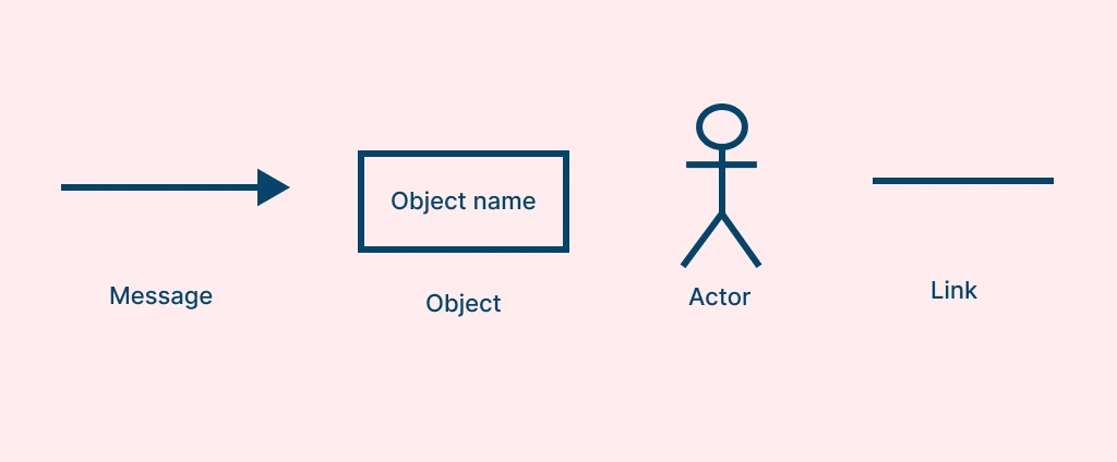
Actors (External Entities)
Actors represent external entities such as users, organizations, or external systems that interact with the system from outside its boundary. They initiate or receive messages and help show how real-world users or systems trigger object interactions. Actors are typically drawn as stick figures connected to the first object they communicate with.
Objects
Objects in a collaboration diagram are represented by rectangles labeled in the format objectName : ClassName (for example, customer : User). They depict instances of classes that interact with one another to perform a specific process or function within the system.
Links (Associations)
Links are shown as solid lines connecting objects or actors, representing communication paths or relationships between them. These lines illustrate how messages travel and how objects are associated during interaction.
Messages
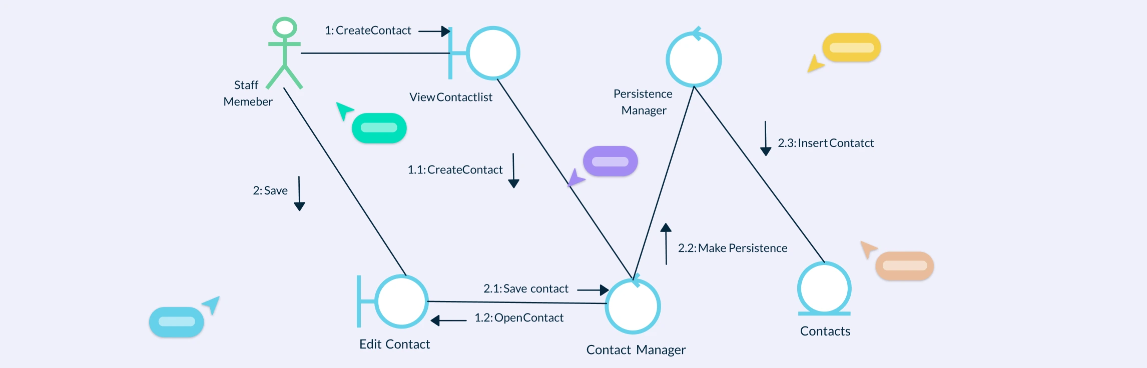
Messages are displayed as labeled arrows placed along the links, showing the direction of communication and the order of execution. Each message includes a sequence number and message name (for example, 1: validateLogin(), 2: fetchData()), indicating the flow and structure of object interactions.
Message Sequence Numbers
Each message is assigned a unique number to indicate the order of execution. Hierarchical numbering (such as 1, 1.1, 1.2) helps track complex flows involving multiple message levels.
How to Make a Collaboration Diagram
You can choose from our collection of ready-made communication diagram templates and follow these steps to make your own.
Step 1: Identify the Scenario or Use Case
Start by selecting a specific process or use case to visualize, such as placing an order or logging in to a system. Define the main objective and the interactions that occur during the process.
Step 2: Identify Actors and Objects
List all actors (external users or systems) and objects (instances of classes) that participate in the interaction. Actors initiate actions, while objects collaborate to complete them. Drag and drop actor and object symbols from the shape library. Use smart alignment guides to position them neatly.
Step 3: Define Relationships (Links)
Draw solid lines between actors and objects to represent communication paths. These links indicate how data or control flows between system components. Use Creately’s smart connectors that automatically snap and adjust as you reposition elements, ensuring your links stay organized.
Step 4: Add Messages and Sequence Numbers
Label each link with messages to describe interactions (e.g., 1: validateLogin() or 2: fetchData()) and include sequence numbers to show execution order. Add text labels directly on connectors and enable automatic numbering for messages to maintain clarity in complex interactions.
Step 5: Arrange and Refine the Layout
Place actors outside the system boundary and objects inside the interaction space. Arrange related elements close together to keep the diagram clean and readable. Make sure of Creately’s auto-layout and grid alignment tools to organize your diagram efficiently.
Step 6: Validate Message Flow and Relationships
Review the entire diagram to ensure that message order, direction, and associations accurately represent the system logic. Invite your team to the workspace to verify interactions, add comments, and make instant refinements.
Step 7: Share and Document
Once your diagram is complete, export it or integrate it into your project documentation. Creately lets you share your collaboration diagram using secure links or export it as a PDF, PNG, or SVG for reports and presentations.
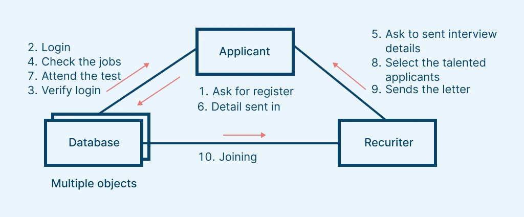
The collaboration diagram example below demonstrates how objects such as Applicant, HR Recruiter and Database interact through message exchanges during the job application process. It highlights object relationships, message flow, and sequencing that collectively illustrate how the system components work together to complete a job submission and review cycle.
Best Practices for Creating Collaboration Diagrams
Start with a clear use case: Focus on a single scenario or process to avoid overcomplicating the diagram.
Use clear, descriptive names for objects: Label objects meaningfully (e.g., orderHandler : OrderProcessor) to clarify their roles.
Keep message flow simple: Limit the number of messages and use hierarchical numbering (e.g., 1, 1.1, 1.2) for clarity.
Follow UML standards: Use consistent symbols like rectangles for objects, solid lines for links, and arrows for messages.
Highlight key interactions only: Include essential communications that define the system’s behavior and omit redundant ones.
Arrange objects logically: Place interacting objects close together and keep actors on the outer edges for readability.
Validate relationships and message order: Ensure each interaction is relevant and the sequence accurately reflects system behavior.
Use color and grouping: Apply color coding or boundary boxes to visually organize related objects or subsystems.
Collaborate and iterate: Review the diagram with stakeholders to refine interactions and improve accuracy.
Use Cases of Collaboration Diagrams
Model specific use case scenarios: Visualize how system components interact to accomplish a business process or system event.
Design interaction logic: Map message exchanges that occur between objects to achieve a defined goal or operation.
Analyze system behavior: Explore how responsibilities are distributed across collaborating objects in different situations.
Validate communication flow: Ensure message sequences and relationships correctly implement intended system logic.
Support object-oriented analysis: Identify objects, classes, and relationships essential for fulfilling functional requirements.
Document system workflows: Capture real interaction patterns for reference in system documentation or stakeholder communication.
Optimize performance: Detect redundant or inefficient object interactions and improve message routing.
Assist in test case creation: Derive interaction-based test scenarios directly from the collaboration logic.
Free Communication Diagram Templates to Get Started


FAQs about UML Collaboration Diagrams
What is the difference between a Collaboration Diagram and a Communication Diagram in UML?
What is the difference between a Sequence Diagram and a Collaboration Diagram in UML?
Can one object send multiple messages in a Collaboration Diagram?
Can Collaboration Diagrams be used for complex systems?
Resources
Kollmann, R, and M. Gogolla. Capturing Dynamic Program Behaviour with UML Collaboration Diagrams. 10 July 2003, pp. 58–67, https://doi.org/10.1109/csmr.2001.914969.
Purchase, H.C., et al. “UML Collaboration Diagram Syntax: An Empirical Study of Comprehension.” Proceedings First International Workshop on Visualizing Software for Understanding and Analysis, https://doi.org/10.1109/vissof.2002.1019790.