Understanding how different parts of a system interact is essential for effective software design, and that’s where UML Communication Diagrams come in. In this guide, we’ll explore what a Communication Diagram is, its purpose, key elements, and how to create one effectively.
Communication Diagram Definition
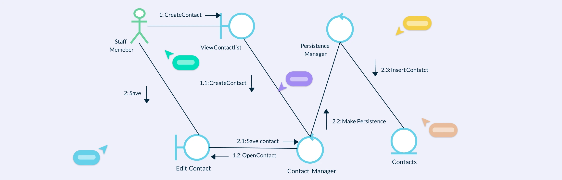
A Communication Diagram is a type of UML behavioral diagram that shows how objects interact through message exchanges to perform a specific function or process. It emphasizes the relationships and communication paths between objects, illustrating how data and control flow within a system. By numbering messages to indicate sequence, UML communication diagrams provide a clear view of object collaborations and system logic, making them valuable for both analysis and design.
Purpose of a Communication Diagram in UML
Visualize object interactions: Show how different objects communicate to perform specific functions or achieve system goals.
Highlight relationships: Emphasize structural links and dependencies between objects within a system.
Clarify message flow: Illustrate how messages are passed between objects to complete a process or operation.
Simplify system understanding: Make complex interactions easier to interpret for developers, analysts, and stakeholders.
Support design and analysis: Help identify collaboration patterns, potential bottlenecks, and opportunities for optimization.
Complement sequence diagrams: Provide an alternative view that focuses on relationships rather than the timing of events.
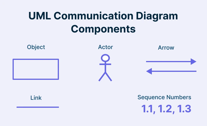
Key Components of a UML Communication Diagram
Actors
Actors represent the users or external entities that interact with the system, such as people, organizations, or other systems. They are typically placed at the top left of the diagram, marking the starting point of interactions. Human actors are shown as stick figures, while non-human ones use distinct shapes. Each actor should be clearly labeled and styled consistently to maintain readability and uniformity across the diagram.
Objects
Represent the entities or instances that interact within the system. Each object is typically shown inside a rectangle with its name and class.
Links
Straight lines that show the communication paths connecting objects, indicating that they can exchange messages. If two objects are not connected by a line, they are considered independent within the system.
Arrows
Show the direction of message flow between linked objects, clarifying who initiates and who receives each message.
Sequence Numbers
Indicate the order in which messages are sent, helping trace the logical flow of communication. Use decimal notation (e.g., 1.1, 1.2, 1.3) to group related messages under a parent message. Always start numbering at 1 and continue sequentially.
Messages
Represent the flow of information between objects, often labeled with numbers to show the order of interactions. Messages should follow UML naming conventions, using camelCase (e.g., 1.1: inputPin).
How to Draw a Communication Diagram
Step 1: Identify the Scenario
Define the process or use case you want to illustrate such as a login flow or data exchange. Start with one of Creately’s pre-built communication diagram templates that you can easily customize to fit your scenario, keeping the diagram focused and aligned with your objectives.
Step 2: Determine the Actors and Objects
List all actors (users or external systems) and objects (components or classes) involved in the interaction. Use consistent shapes and naming conventions to represent them, ensuring the diagram remains clear and easy to interpret.
Step 3: Establish Relationships with Links
Connect actors and objects that communicate with one another using links or lines. These represent potential message paths within the system. Keep the layout clean, avoid unnecessary connections and only link elements that directly interact.
Step 4: Define Message Flow with Arrows
Add arrows along the connecting lines to show the direction of communication. Make it clear who sends and who receives each message. Maintain consistent arrow styles, spacing, and formatting for a professional appearance.
Step 5: Add Sequence Numbers
Label each message with a sequence number (e.g., 1, 1.1, 1.2) to indicate the order of interactions. This numbering helps trace the logical flow of communication and can serve as a reference when converting the UML communication diagram into a sequence diagram.
Step 6: Label Messages Clearly
Add short, descriptive message labels next to each arrow, such as 1.1: validateInput. Follow UML naming conventions using camelCase, and maintain uniform font size and style for readability and consistency.
Step 7: Refine and Validate the Diagram
Once the diagram is complete, review it for clarity and accuracy. Arrange elements logically—usually top-to-bottom or left-to-right—and minimize crossing lines. Use Creately’s smart alignment, snapping, and real-time collaboration features to refine layouts, collect instant feedback from your team, and ensure all actors, objects, and messages accurately reflect the system’s workflow before finalizing the diagram.
Best Practices for Making Communication Diagrams
Be Clear and Concise: Use simple, descriptive, and unique names for messages and objects. Avoid cluttering the diagram with unnecessary details that obscure understanding.
Organize Objects Logically: Arrange objects in a way that reflects their real-world or logical relationships. A well-structured layout improves readability and helps others quickly grasp interaction flows.
Maintain Consistent Notation: Apply uniform symbols, labels, and numbering throughout the diagram. Consistency ensures that all team members interpret the diagram the same way.
Highlight Key Interactions: Focus on the most critical communications between objects. Removing minor or repetitive interactions helps simplify the diagram and emphasize core behavior.
Validate with Stakeholders: Review the diagram with designers, developers, and other relevant stakeholders. Their feedback helps confirm that all important interactions are captured accurately.
Document Assumptions and Notes: Add brief annotations to explain complex or conditional interactions. This helps clarify intent and supports future maintenance.
Keep Diagrams Up to Date: Update the diagram whenever system behavior or object relationships change to maintain its accuracy and usefulness over time.
Benefits of a Communication Diagram
Enhances Collaboration Across Teams: Serves as a common visual language that bridges communication between developers, analysts, and non-technical stakeholders.
Improves Documentation and Knowledge Sharing: Provides a clear visual reference for system interactions, making onboarding and future maintenance easier.
Detects Design Issues Early: Helps identify unnecessary dependencies, missing connections, or inefficiencies before development begins.
Streamlines Maintenance and Updates: Offers a quick way to revisit and adjust interaction flows when systems evolve, ensuring continued accuracy.
Supports Better Decision-Making: Enables teams to evaluate design trade-offs, communication patterns, and architecture improvements based on visual insights.
Integrates Well with Other UML Tools: Complements broader UML modeling efforts by connecting behavioral insights with structural diagrams for a complete system view.
Challenges with Communication Diagrams
While communication diagrams are valuable for illustrating object interactions, they also present several challenges during modeling and maintenance:
Managing Complexity
As systems grow in size and functionality, communication diagrams can become cluttered with numerous objects and message links. This makes it difficult to trace interactions or identify system behavior without visual overload.
Ensuring Accuracy
Because communication diagrams rely on precise relationships between objects, even small updates to system requirements or data flow can introduce inconsistencies. Keeping them synchronized with evolving designs requires continuous updates and validation.
Lack of Timing Information
Unlike sequence diagrams, communication diagrams do not emphasize the order or timing of messages. This absence of temporal context can make it harder to interpret the sequence of events or analyze performance-related interactions.
Scalability Limitations
When modeling complex systems with many interacting objects, diagrams can become too dense to navigate. Zooming into specific sections or maintaining readability across multiple layers often requires breaking the model into smaller diagrams.
Integration with Other UML Diagrams
Aligning communication diagrams with related UML models such as sequence, class, or activity diagrams can be challenging. Inconsistencies between diagram types may lead to redundant or conflicting representations of the same interactions.
When to Use UML Communication Diagrams
During System Design
Use UML communication diagrams when defining how system components interact to achieve specific behaviors or processes. They help visualize collaboration patterns and ensure all necessary relationships are accounted for.
When Analyzing Object Interactions
Ideal for examining how multiple objects or modules exchange messages to perform a function, especially in complex systems with many dependencies.
As an Alternative to Sequence Diagrams
Use them when you want to highlight relationships and structure rather than timing. Communication diagrams focus on connections and message flow, making them easier to read for high-level design discussions.
For Documenting System Behavior
Helpful in creating clear, visual documentation of system interactions that can be referenced throughout the software development lifecycle.
When Optimizing or Refactoring Systems
UML communication diagrams can be used to identify redundant links, inefficient communication paths, or missed interactions during system improvement or refactoring efforts.
In Collaborative Design Reviews
Particularly valuable in team discussions or design reviews where multiple stakeholders need to understand how different system elements work together.
Communication Diagram Vs. Sequence Diagram
Both Communication and Sequence Diagrams are interaction diagrams in UML that illustrate how objects collaborate to achieve a process. They differ mainly in what they emphasize, structure versus timing.
Aspect | Communication Diagram | Sequence Diagram |
Primary Focus | Highlights the structural relationships and message exchanges between objects. | Emphasizes the time-based sequence and order of interactions between objects. |
Best For | Understanding how objects are linked and interact within a system’s architecture. | Understanding when and in what order events or messages occur during execution. |
Temporal Information | Does not explicitly represent timing or duration of actions. | Clearly depicts chronological order and lifeline activation over time. |
Complexity Handling | Easier for showing object connections, but can get cluttered as interactions grow. | Easier for visualizing control flow, but may become lengthy for complex scenarios. |
Use Case | Ideal for getting a structural overview or verifying message links between components. | Ideal for detailed behavioral analysis or debugging the flow of operations. |
Communication Diagrams provide a clear view of how objects collaborate through message exchanges, helping teams understand system interactions more effectively. They complement other UML diagrams by focusing on the relationships and message flow between components. With Creately’s UML Diagram Tool, you can effortlessly build communication diagrams alongside other UML types to design, document, and optimize your system architecture in one collaborative workspace.
Free Communication Diagram Templates to Get Started


FAQs about UML Communication Diagrams
How is a Communication Diagram different from a Sequence Diagram?
Can Communication Diagrams be linked with other UML diagrams?
Can I use a communication diagram for a high-level view?
How to express loops in Communication Diagrams?
Resources
Alsaadi, Ahmad. “The UML Communication Diagram Revisited.” International Conference on Software Engineering Advances (ICSEA 2007), Aug. 2007, https://doi.org/10.1109/icsea.2007.76.
Parbati Mahanto, et al. Achieving MC/DC Using UML Communication Diagram. 1 Dec. 2018, https://doi.org/10.1109/icit.2018.00026.