Package Diagram Definition
A package diagram in UML (Unified Modeling Language) is a structural diagram that groups related elements such as classes or components into logical units called packages. It shows how these packages are organized and depend on each other, offering a clear view of a system’s structure. By grouping related parts, package diagrams simplify complex designs, promote modularity, and ensure a clean separation of responsibilities within large software systems.


Key Elements of a UML Package Diagram
Package
The fundamental unit of a package diagram, representing a logical container that groups related elements such as classes, interfaces, or subsystems. It helps organize large systems into modular and manageable units.
Namespace
Defines the unique name or identifier of a package, ensuring each package can be distinctly recognized within a UML model.
Dependency
Represents a relationship in which one package relies on another, meaning that changes in one may affect the other’s functionality. Common types of dependencies include,
Package Merge: Combines the contents of one package with another, unifying their elements into a single structure.
Package Import: Allows one package to access another’s public elements without merging their contents.
Access: Permits a package to reference elements from another without formally importing them, usually for limited or read-only interaction.
Usage: Indicates that one package uses or depends on the functionality of another.
Stereotype
A UML mechanism used to specify the exact type or intent of a dependency or relationship. They help clarify how packages interact and the purpose of their connections.
Element
Refers to an individual component within a package such as a class, interface, or subsystem that defines part of the system’s structure or behavior.
Constraint
Specifies conditions or rules that govern how a package or its elements should behave, helping maintain design consistency and integrity.
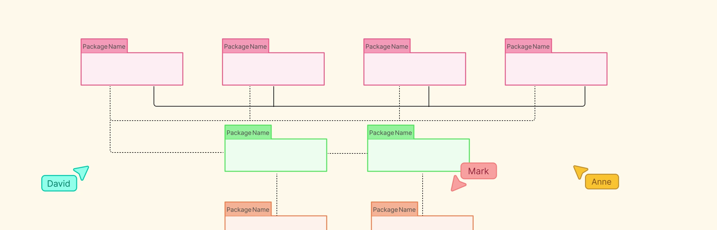
Package Diagram Notation and Symbols Explained
In UML, package diagrams use standardized notations to visually represent how system components are grouped and related. These symbols make it easier to interpret structure, dependencies, and visibility at a glance.
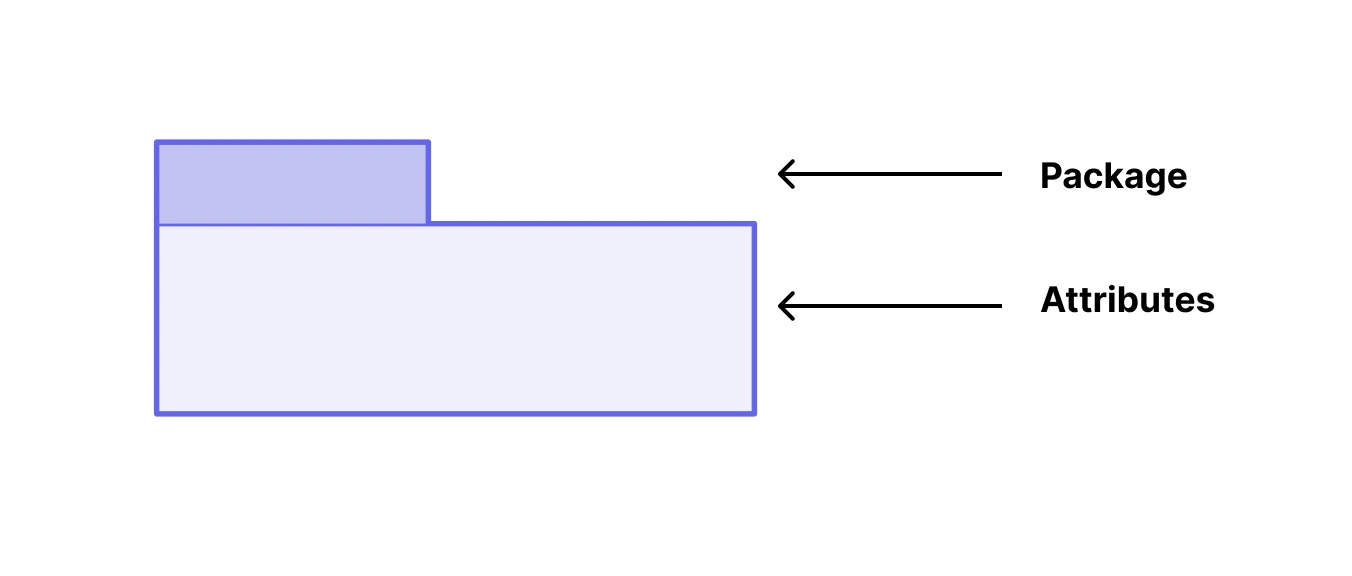
Package
A package is represented as a folder-shaped rectangle with a small tab in the upper-left corner displaying its name or namespace. The folder may contain elements like classes, interfaces, or subpackages, visually organizing related items under one module.
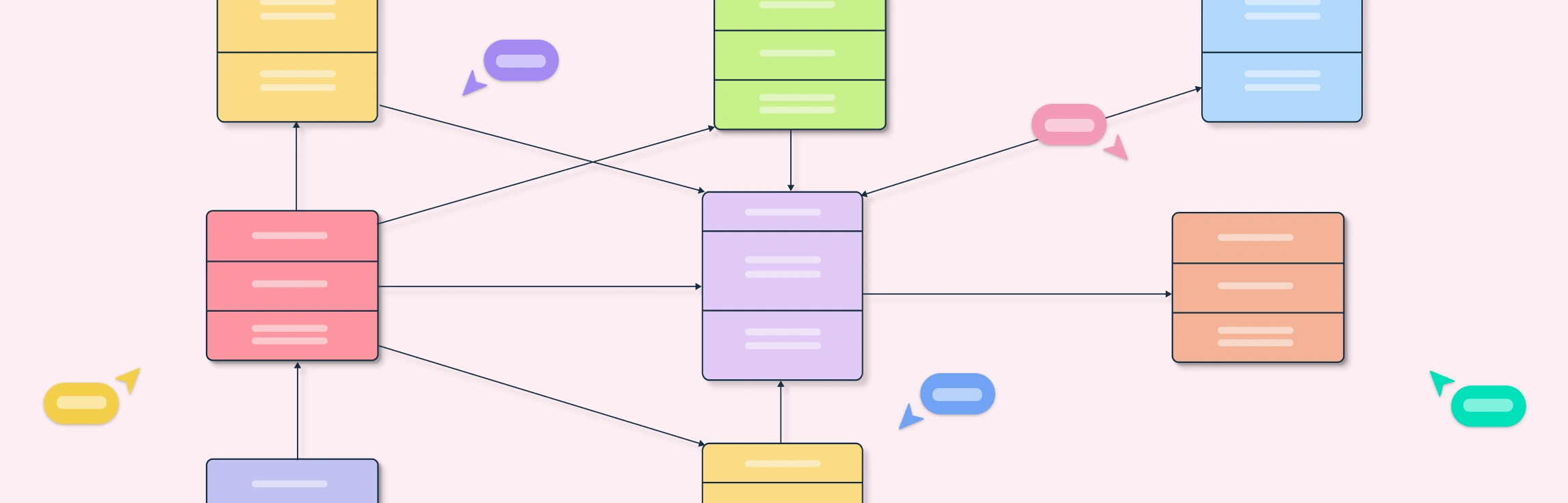
Dependency Arrows
In UML package diagrams, dependencies (relationships) are shown using dashed arrows that point from the client package (the one depending) to the supplier package (the one being depended on). These arrows illustrate how one package relies on another to function.
![]()
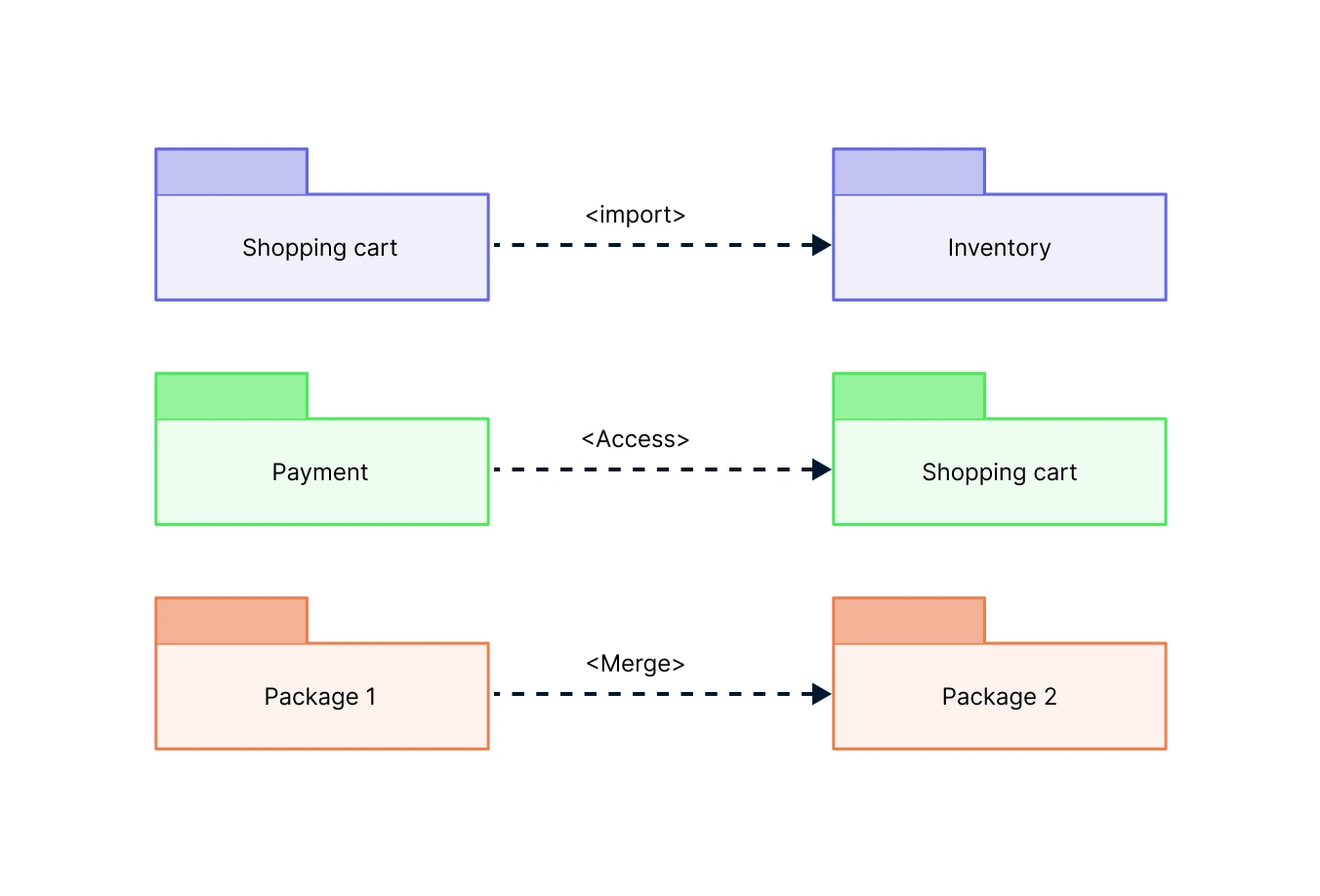
Stereotypes (Dependency Notation)
A stereotype is a label written within double angle brackets (<< >>). These stereotypes clarify the purpose of the relationship and the level of coupling between packages.
1. « import »
Shows that a client package imports a supplier package, making its public elements directly available in the client’s namespace. This allows the client to reference those elements without qualification.
Example: A User Interface package imports a UI Components package to use shared elements like buttons, forms, and menus across screens.
2. « access »
Represents a relationship where a package can access public elements of another package without fully importing them. It’s a weaker dependency, often used for read-only or reference access.
Example: A Reporting package accesses a Sales Data package to read data summaries but does not import or modify its classes directly.
3. « merge »
Combines two or more packages into a single namespace, typically used in metamodeling to unify related definitions.
Example: Merging multiple payment method packages (CreditCard, PayPal, BankTransfer) into one Payment package.
Why Package Diagrams are Important
Simplify Complex Systems
Package diagrams break down large and intricate software architectures into smaller, more understandable modules. By grouping related elements into logical units, teams can focus on one part of the system at a time, making analysis, design, and debugging far more manageable.
Promote Modular Design
They encourage a modular approach where each package has a clear purpose and limited responsibility. This separation improves maintainability, scalability, and flexibility, allowing updates or replacements to be made without disrupting the entire system.
Clarify Dependencies
Package diagrams clearly illustrate how different subsystems or modules depend on one another. This visibility helps developers reduce unnecessary coupling, detect circular dependencies, and ensure a clean architecture where data and logic flow efficiently.
Enhance Communication
By providing a visual overview of the system’s structure, package diagrams help bridge the gap between technical and non-technical stakeholders. Architects, developers, and project managers can all use them to discuss design decisions and system organization with clarity.
Support Reusability
Well-structured packages can be easily reused in other systems or projects. A common library or shared service package can be integrated wherever needed, reducing duplication and speeding up development.
Aid in System Organization
Package diagrams establish clear boundaries and ownership between different system layers or modules. This helps teams collaborate efficiently, manage version control, and align their work with the overall architectural plan.
Free Package Diagram Templates to Get Started


FAQs about Package Diagrams
What’s the difference between a package and a module?
Can package diagrams show subpackages or hierarchies?
Can a merge relation in a UML Package Diagram lead to multiple inheritance?
Should I draw related packages inside a larger package or use an aggregation/composition arrow to show containment?
Resources
Handigund, Shivanand M., et al. “An Automated Methodology for the Design of Usecase Package Diagram.” 2012 World Congress on Information and Communication Technologies, Oct. 2012, pp. 309–314, https://doi.org/10.1109/wict.2012.6409094.
Stefano Spaccapietra, et al. Conceptual Modeling - ER 2002. Springer, 30 June 2003.